00198829-01_SM_X-Series-S_Hxxxx_EN.pdf - 第283页
9 Component feeding 9.1 Cutter Service Manual SIPLACE X-Series S (from Hxxxx) 01/2021 283 9 Component feeding DANGER Observe User Manual ► Please observe the safety instructions in the user manual for all work! 9.1 Cutte…

8 Head exchange
8.10 Calibration
282 Service Manual SIPLACE X-Series S (from Hxxxx) 01/2021
9 Component feeding
9.1 Cutter
Service Manual SIPLACE X-Series S (from Hxxxx) 01/2021 283
9 Component feeding
DANGER
Observe User Manual
► Please observe the safety instructions in the user manual for all work!
9.1 Cutter
DANGER
Observe User Manual
► Please observe the safety instructions in the user manual for all work!
WARNING
Risk of injury when working near the cutter.
When working in the area of the tape cutter, move the component trolley out of the machine
and disconnect the machine from the mains supply and the compressed air supply.
► Wait until the operating pressure has dropped to 0 MPa.
► Pull one of the thinner hoses off the Y distributor on the cutter, to vent the pneumatic
lines and the cutter (see 9.1.2
"Venting compressed air at the cutter" [}284]).
► After completing work to the cutter, you will need to connect the hose again.
► Always secure the machine against unauthorized reactivation.
► Do not reach into the tape cutter.
CAUTION
Risk of injury when performing service work on the tape cutter.
Never support the tape cutter on your body, e.g. on your knees or thighs. Do not place your
feet under the tape cutter.
► Wear appropriately thick protective gloves.
► Only hold and carry the cutter on the outer left and righthand parts.
9.1.1 Cutter
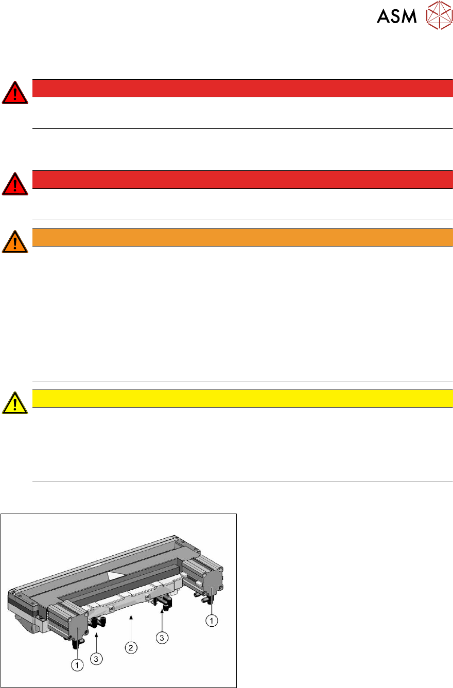
Fig.379: Overview of cutter [03066690‑xx]
1. Short stroke cylinder
2. Electrical connection
3. Solenoid valves
9 Component feeding
9.1 Cutter
284 Service Manual SIPLACE X-Series S (from Hxxxx) 01/2021
9.1.2 Venting compressed air at the cutter
► Switch off the compressed air supply
5.2 "Disabling the compressed air supply" [}86]
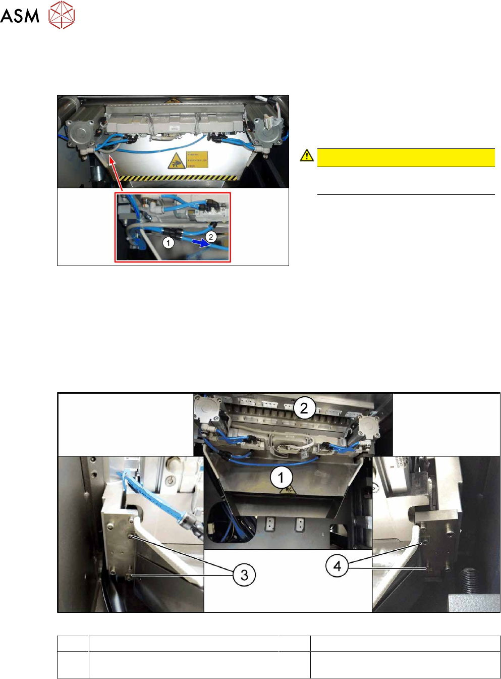
Fig.380: Disconnecting the hose
► Carefully pull one of the two small
hoses(2)
of the Y-piece(1).
This enables any compressed air still
present in the system to be released.
CAUTION!
Risk of injury
The hoses could still be pressurized.
.
9.1.3 Replacing the waste tape slide
Parts, equipment and tools
●
Used tape chute complete [03067460-xx]
●
Allen key set
Overview
Fig.381: Waste tape slide
1 Waste tape slide 2 COT insert
3 Fastening screw for used tape chute, left 4 Fastening screw for used tape chute,
right