00198829-01_SM_X-Series-S_Hxxxx_EN.pdf - 第245页
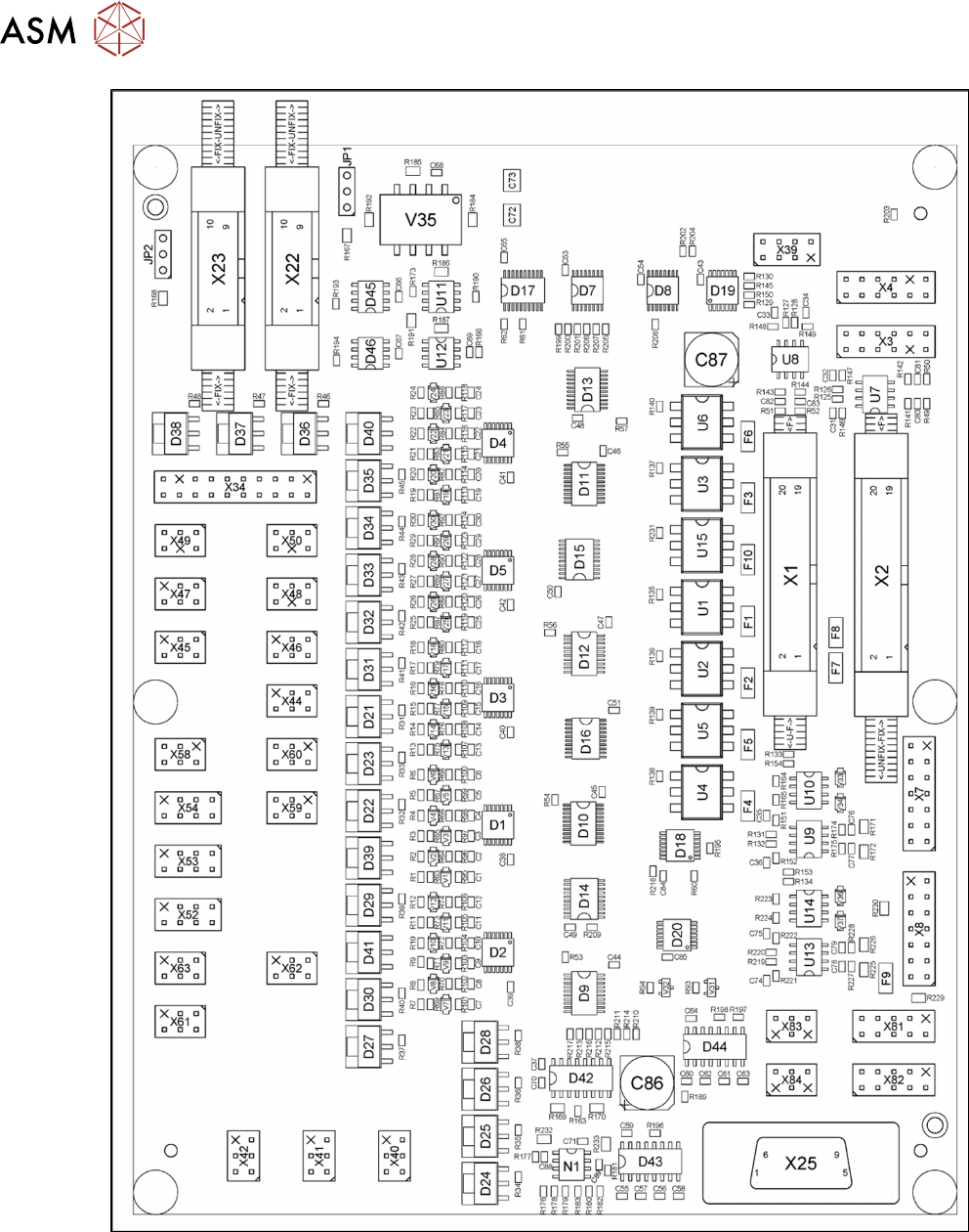
7 Conveyor 7.9 Boards Service Manual SIPLACE X-Series S (from Hxxxx) 01/2021 245 Fig.323: TSP420 machine plate SIPLACE X4 S
7 Conveyor
7.9 Boards
244 Service Manual SIPLACE X-Series S (from Hxxxx) 01/2021
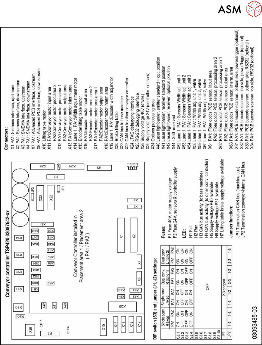
Fig.322: 03087641-02
7 Conveyor
7.9 Boards
Service Manual SIPLACE X-Series S (from Hxxxx) 01/2021 245
Fig.323: TSP420 machine plate SIPLACE X4 S
7 Conveyor
7.10 Conveyor sides
246 Service Manual SIPLACE X-Series S (from Hxxxx) 01/2021
7.10 Conveyor sides
7.10.1 Setting the Fixed Conveyor Side
7.10.1.1 Setting the Fixed Conveyor Side on Single Conveyors
CAUTION
Moving the conveyor sides
► The conveyor sides are highly sensitive. Move them very carefully and evenly. Take
special care not to distort the conveyor sides.
Overview
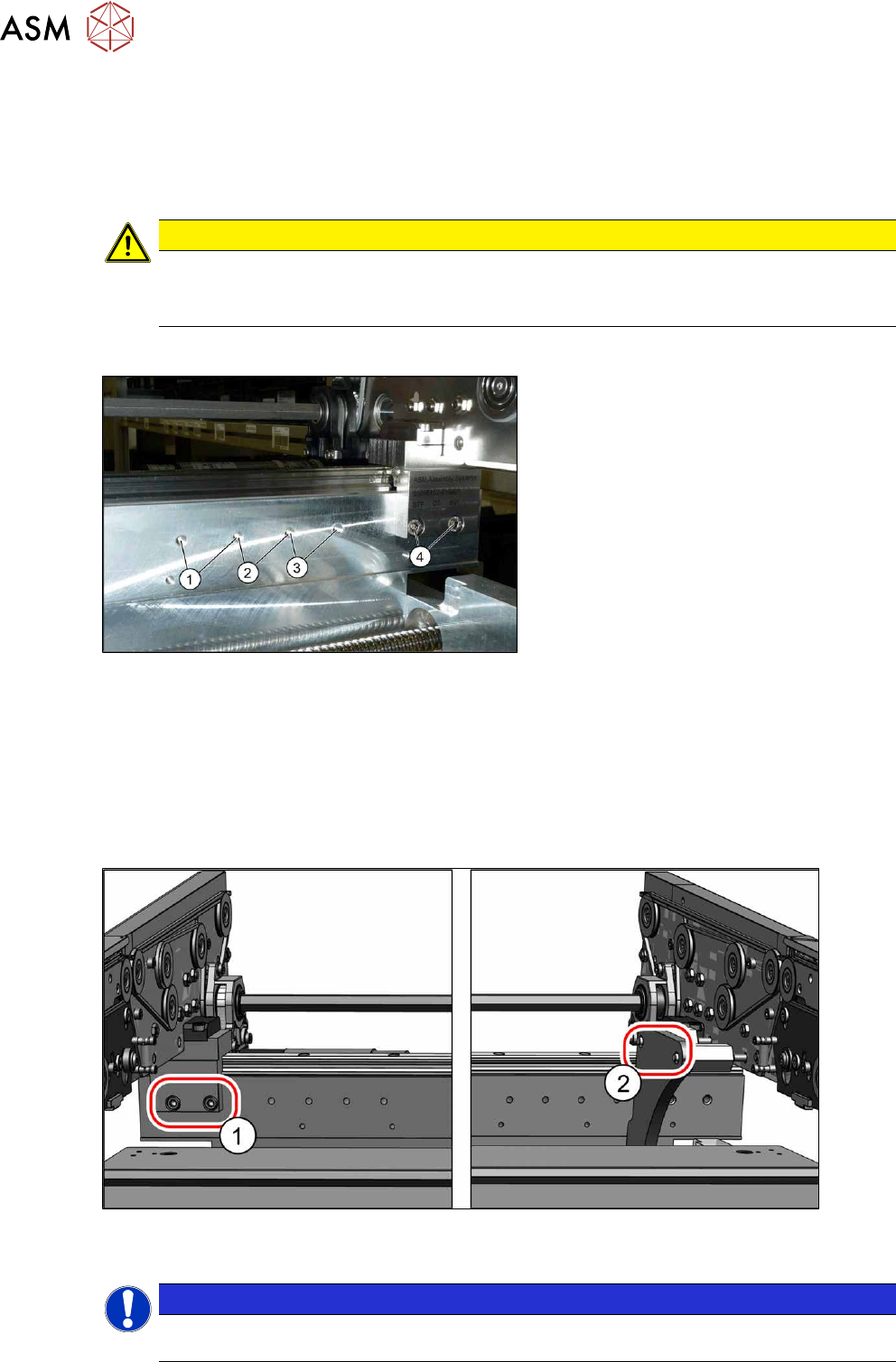
Fig.324: Overview of side wall positions
1. Position 231.0 mm
Max. PCB width: 460mm
2. Position 256.0 mm
Max. PCB width: 560mm
3. Position 281.0 mm
Max. PCB width: 560mm
4. Position 344.0 mm
Max. PCB width: 685mm
The conveyor side is fixed with two fastening
screws each point from (1)
to (4).
Setting
► Use the software to move the conveyor sides into a position which allows you best access.
► Switch off the machine, disconnect it from the power supply and secure it to prevent
unauthorized reactivation.
1.2 "Preparatory work..." [}16]
► Always perform the following three steps immediately at the three holders.
Fig.325: Setting the conveyor side position
► Remove the screws (1) fastening the conveyor side (two screws per holder).
NOTICE
You can also loosen two screws on the connection between the side wall and the flange, to
prevent distortion during movement. The side wall is otherwise very difficult to move.