00198829-01_SM_X-Series-S_Hxxxx_EN.pdf - 第264页
8 Head exchange 8.5 Replacing the SIPLACE C&P20P/M2 264 Service Manual SIPLACE X-Series S (from Hxxxx) 01/2021 Installation ► If you replace the placement head without the component camera, you will need to fit the …
8 Head exchange
8.5 Replacing the SIPLACE C&P20P/M2
Service Manual SIPLACE X-Series S (from Hxxxx) 01/2021 263
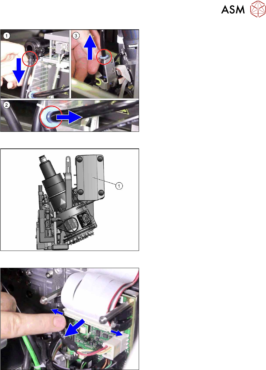
Fig.348: Pneumatic connections
► Disconnect the pneumatic connec-
tions(1)
to(3) from the placement
head.
Fig.349: Cover on intermediate distributor board
► Remove the cover(1) (press studs).
Fig.350: Flat ribbon cable
► Unplug the ribbon cables between the
placement head and the head adapter.
► Open the cable holders and unplug the PCB camera cable from the Vision Head Interface.
While unplugging the cables, press the clamps on both sides of the connectors and open any
cable ties.
► Unscrew all four M4 fastening screws with a long Torx key.
► Carefully lift the placement head out of the locating pins on the head plate and from the hook.
► Placing the head into the head transport box
► If you need to perform further work on this placement head (e.g. replacing spare parts), fit the
placement head to the head mount [03056231-xx].

8 Head exchange
8.5 Replacing the SIPLACE C&P20P/M2
264 Service Manual SIPLACE X-Series S (from Hxxxx) 01/2021
Installation
► If you replace the placement head without the component camera, you will need to fit the old
camera into the new head. In this case a full calibration is necessary. Read the service
manual for your placement head for more information.
► The placement head must be converted using the "Holding circuit assembly/C&P20" kit
[03005123Sxx] or the "Compressed air mode CP20x" kit [03106765‑xx] for compressed air
mode.
► Make sure that the assembly position on the head plate is correct.
► Tighten the four head fastening screws (M4) with a torque of 2.7 Nm.
NOTICE
Various hose lengths on SIPLACE X-Series S
The hose to the pressure control valve will vary in length, depending on the installation loc-
ation (standard gantry or rotated gantry).
► Shorten or replace the hose, where necessary.
Follow the removal instructions in reverse order for further installation.
See also
2 8.9 "Installation Positions on the Head Plate" [}278]
8 Head exchange
8.6 Replacing the SIPLACE C&P20P2
Service Manual SIPLACE X-Series S (from Hxxxx) 01/2021 265
8.6 Replacing the SIPLACE C&P20P2
NOTICE
Retrofitting the SIPLACE C&P20 P2
The SIPLACE C&P20P2 can be retrofitted from machine numbers H1440.
The following prerequisites must be fulfilled:
► The head interface [03091013‑xx] / [03091023‑xx] must have at least FS04.
► The gantry sensor [03071974‑xx] must have at least FS02.
► The MGCU-3 [03103477-xx] must have at least FS04.
► The MGCU-2 [03117531‑xx] must have at least FS03.
► An X-FCU with 80 MHz [03170613-xx] must be fitted.
Parts
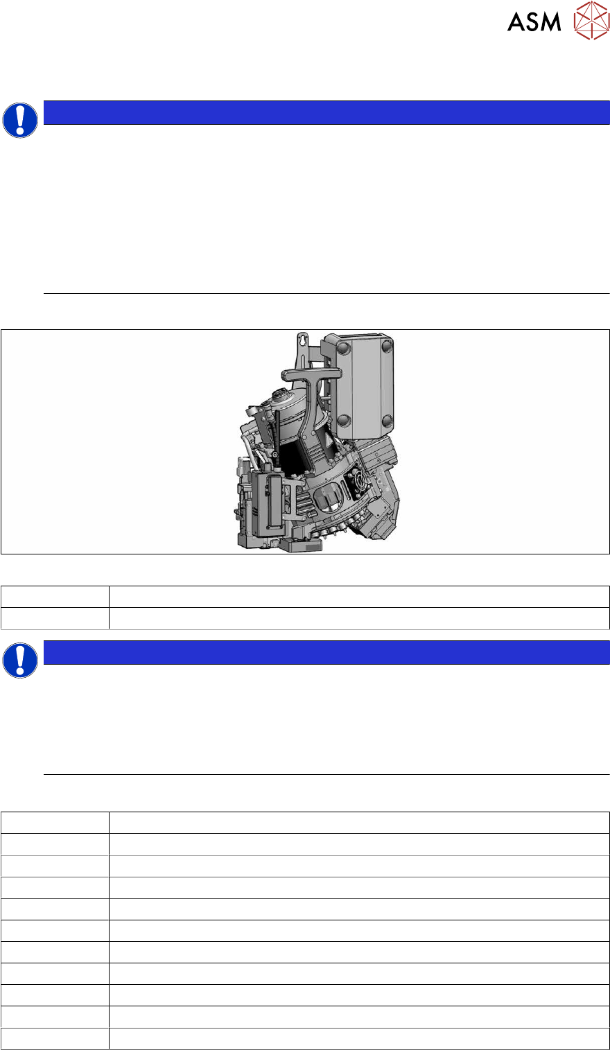
Fig.351: SIPLACE C&P20P2 with camera
03147200-xx SIPLACE C&P20P2 placement head with camera
03126608-xx SIPLACE C&P20P2 placement head without camera
NOTICE
Vacuum pump/compressed air operation
As a spare part, the head is prepared for vacuum pump operation and is fitted with the
"Aperture ring assembly C&P20 P" [03116883‑xx].
► The SIPLACE C&P20P2 must be converted with the conversion kit "Compressed air
C&P20x" [03106765‑xx] or with the "Holding circuit assembly C&P20" [03005123Sxx]
for operation in compressed air mode.
Equipment and tools
03078400‑xx Torque screwdriver ESD 1.0-5.0 Nm
03078706‑xx Bitholder for screwdriver TorqueVario
03073256‑xx Extension/ straight TX20
03156306-xx Component sensor protective cap
03157023‑xx Calibration piece SST48/49
03034148-xx Calibration part version SST23
03162648-xx Packaging SIPLACE C&P20 P2 assembly (transport box)
00198607-xx Service manual "SIPLACE C&P20P2 head"
00353832-xx Allen key set
Wire cutters
Cable tie