00198829-01_SM_X-Series-S_Hxxxx_EN.pdf - 第333页
9 Component feeding 9.3 X-Series Component Trolley Service Manual SIPLACE X-Series S (from Hxxxx) 01/2021 333 9.3.4 Replacing the Guide Profile/Entering Guide Feeder Parts Fig.468: Entering guide and guide profile 03002…
9 Component feeding
9.3 X-Series Component Trolley
332 Service Manual SIPLACE X-Series S (from Hxxxx) 01/2021
Removal/installation
► Remove the waste tape container (1) and empty it.
► Refit the waste tape container. This makes sure that any parts which fall down are not lost.
NOTICE
Waste tape container
You can use the waste tape container as a surface on which to place small parts (tension
springs, locking latches etc.).
► Remove the screws fastening the cover plate locking rail [03077142-xx](2). Use a suitable
Phillips screwdriver to avoid damaging the screws.
4
5
1
3
2
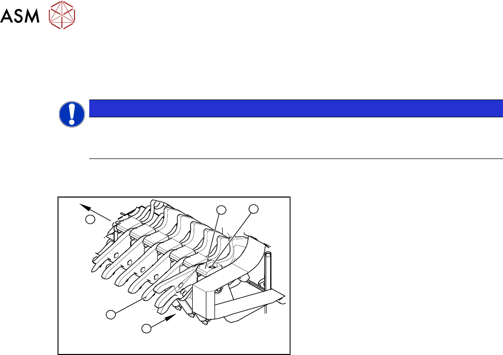
Fig.467: Removing the locking latch
► Unhook all tension springs (1) from the
locking latches (2)
.
► Remove the screws (3) fastening the
pressure plates(4)
.
► Pull out the locking latches with the
shaft(5)
.
► The locking latches can now be pushed
off the shaft.
► Return the locking latches, including
the new one, to the shaft.
► Fit the locking latches and shaft.
► During reassembly, take care to keep the pressure plates in their correct position (4). These
are not symmetrical and will not hold the shaft properly if placed in a certain (incorrect) posi-
tion.
► When tightening the fastening screws (3), make sure that the pressure plates (4) are not at an
incorrect angle and that the locking latches do not jam.
► Hook the tension springs (1) back up.
► Refit the cover.
9 Component feeding
9.3 X-Series Component Trolley
Service Manual SIPLACE X-Series S (from Hxxxx) 01/2021 333
9.3.4 Replacing the Guide Profile/Entering Guide Feeder
Parts
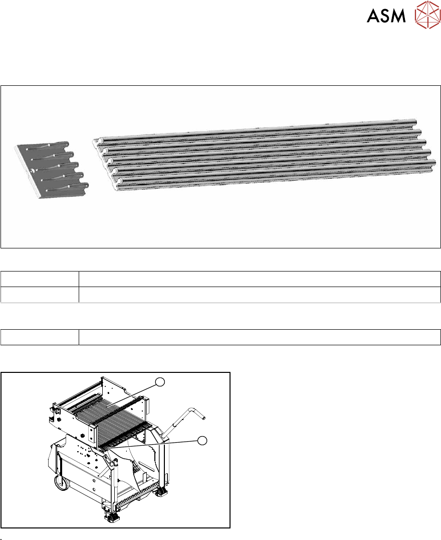
Fig.468: Entering guide and guide profile
03002898-xx Short guide profile
03039368-xx Feeder entering guide
Equipment and tools
00353832-xx Allen key set
Overview
1
2
Fig.469: Guide profiles on component trolley
1. Short guide profile
2. Feeder entering guide
The short guide profiles are fixed from
above with one screw each.
The feeder entering guide is screwed into
place from below.
9 Component feeding
9.3 X-Series Component Trolley
334 Service Manual SIPLACE X-Series S (from Hxxxx) 01/2021
9.3.5 Replacing the bearing assembly
Parts
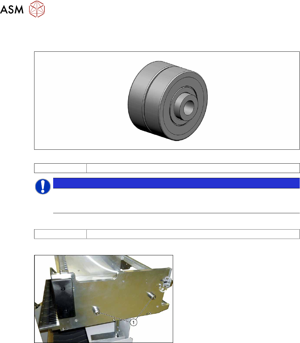
Fig.470: Bearing assembly
03103947-xx Bearing assembly
NOTICE
Replacing all sleeves
We recommend that you always replace all bearing assemblies belonging to a changeover
table at the same time.
Tools
00334892-xx Loctite 243
Overview
Fig.471: Centering sleeves
1. Bearing assembly (four per table)
Removal
► Remove the screw fastening the bearing assembly and then remove the bearing assembly.
Installation
Follow the removal instructions in reverse order for installation. Also observe the following instruc-
tions:
► Secure the screw with Loctite243.