00198829-01_SM_X-Series-S_Hxxxx_EN.pdf - 第371页
9 Component feeding 9.6 Smart Pin Support Service Manual SIPLACE X-Series S (from Hxxxx) 01/2021 371 9.6.12 Replacing the top sensor Parts, equipment and tools ● Top sensor [03093273Sxx] ● Assembly instructions "Sma…
9 Component feeding
9.6 Smart Pin Support
370 Service Manual SIPLACE X-Series S (from Hxxxx) 01/2021
9.6.11 Replacing the tension spring
Parts, equipment and tools
●
Tension spring (reduced eyelet) [03089675-xx]
●
Circlip pliers size 0 (supplier: http://www.hoffmann-tools.com – item no.:719770 J0)
●
Assembly instructions "Smart Pin Support" for SIPLACE X‑SeriesS [DEEN:00197394‑xx]
Removal
► Switch off the machine, disconnect it from the power supply and secure it to prevent
unauthorized reactivation.
1.2 "Preparatory work..." [}16]
► Remove the Pin Picker.
9.6.1 "Replacing the Pin Picker Assembly" [}357]
► Remove the linear guide. For more information, read section 9.6.4 "Replacing the linear
guide" [}361]. You do not need to remove the front and back sections of the cylinder.
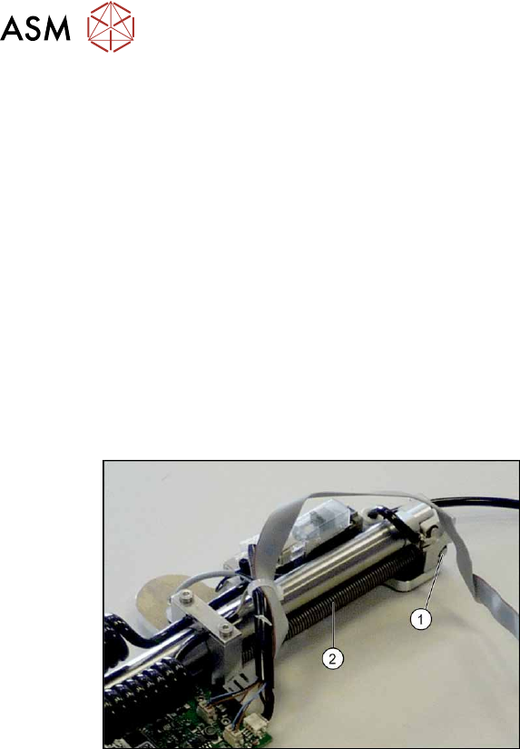
Fig.531: Tension spring
► Remove the circlip on the holding
bolt(1)
of the tension spring(2) and
then pull out the holding bolt.
► Remove the tension spring.
Installation
Follow the removal instructions in reverse order for installation. Observe the following note:
► When you screw in the linear guide trolley, press it to the left, against the stop edge, so that it
lies flush against the base plate.
9 Component feeding
9.6 Smart Pin Support
Service Manual SIPLACE X-Series S (from Hxxxx) 01/2021 371
9.6.12 Replacing the top sensor
Parts, equipment and tools
●
Top sensor [03093273Sxx]
●
Assembly instructions "Smart Pin Support" for SIPLACE X‑SeriesS [DEEN:00197394‑xx]
Overview
Fig.532: Sensors
1. Control board
2. Fastening screw for top sensor
3. Fastening screw for bottom sensor
Removal
► Switch off the machine, disconnect it from the power supply and secure it to prevent
unauthorized reactivation.
1.2 "Preparatory work..." [}16]
► Remove the Pin Picker.
9.6.1 "Replacing the Pin Picker Assembly" [}357]
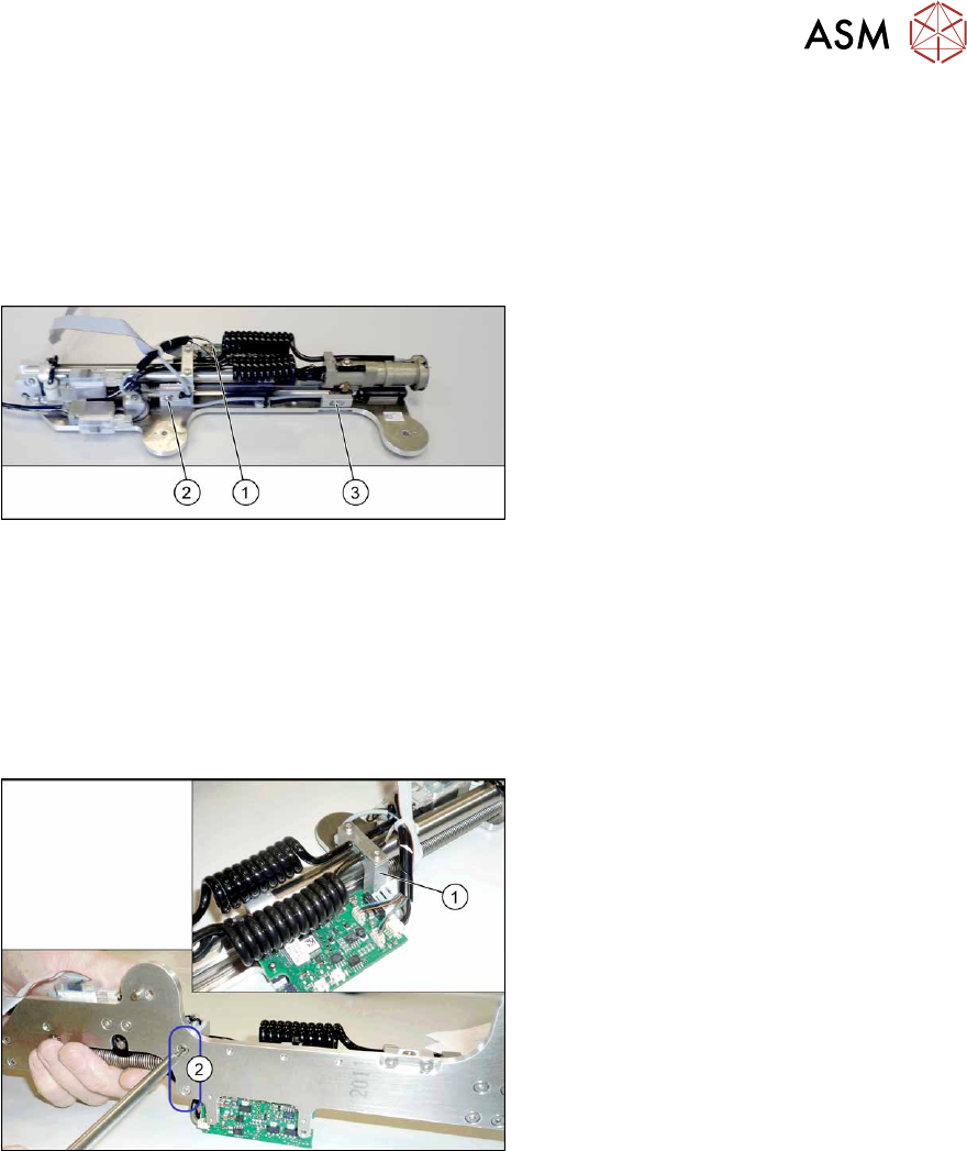
Fig.533: Screws fastening the guide
► Remove the two screws(2) fastening
the pneumatic cylinder guidance(1)
.
► Remove the screws holding the sensor.
► Unthread the sensor cable as far as the
board. Open the corresponding cable
ties to help you, if needed.
► Unplug the sensor cable from the
board. You may want to mark the posi-
tion to make clear assignment easier
later on.
Installation
Follow the removal instructions in reverse order for installation. Also observe the following instruc-
tions:
► Fasten the sensor in the center of the slot.
► Check that the sensors switch properly.
The switch tag of the linear guide must have between 0.7 and 1.4 mm space to the sensor
above or below.
The top sensor must switch after 2mm when travelling downwards.
► Replace any opened cable ties.
9 Component feeding
9.6 Smart Pin Support
372 Service Manual SIPLACE X-Series S (from Hxxxx) 01/2021
9.6.13 Replacing the bottom sensor
Parts, equipment and tools
●
Inductive sensor assembly, bottom SPS [03090192Sxx]
●
Assembly instructions "Smart Pin Support" for SIPLACE X‑SeriesS [DEEN:00197394‑xx]
Overview
Fig.534: Sensors
1. Control board
2. Fastening screw for top sensor
3. Fastening screw for bottom sensor
Removal
► Switch off the machine, disconnect it from the power supply and secure it to prevent
unauthorized reactivation.
1.2 "Preparatory work..." [}16]
► Remove the Pin Picker.
9.6.1 "Replacing the Pin Picker Assembly" [}357]
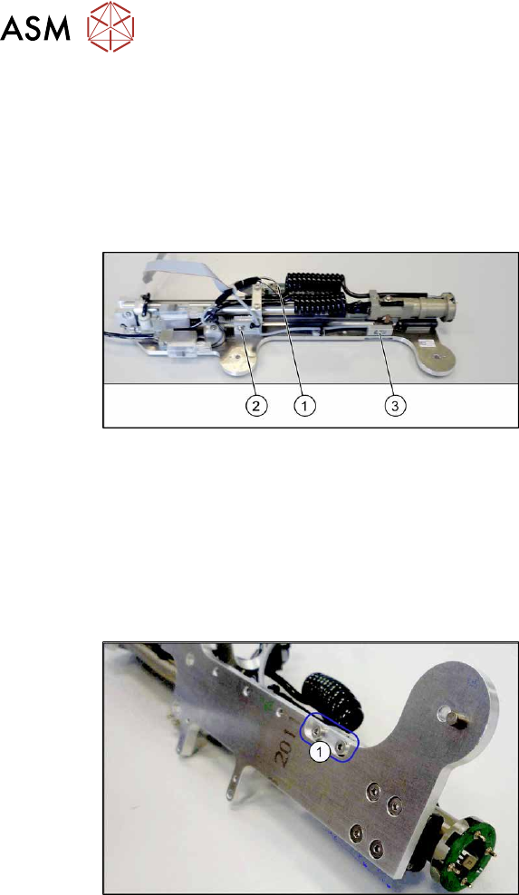
Fig.535: Screws fastening the sensor mount
► Remove the two screws(1) fastening
the sensor mount.
► Remove the screws holding the sensor.
► Unthread the sensor cable as far as the board. Open the corresponding cable ties to help you,
if needed.
► Unplug the sensor cable from the board. You may want to mark the position to make clear as-
signment easier later on.
Installation
Follow the removal instructions in reverse order for installation. Also observe the following instruc-
tions:
► Fasten the sensor in the center of the slot.
► Check that the sensors switch properly.
The switch tag of the linear guide must have between 0.7 and 1.4 mm space to the sensor
above or below.
The bottom sensor must switch after 112 mm when travelling downwards.
► Replace any opened cable ties.