00198829-01_SM_X-Series-S_Hxxxx_EN.pdf - 第319页
9 Component feeding 9.2 COT insert Service Manual SIPLACE X-Series S (from Hxxxx) 01/2021 319 Removal ► Dismantle the feeder unlock device (see 9.2.5 "Replacing the 40-fold feeder unlock device" [ } 317] ). Fi…
9 Component feeding
9.2 COT insert
318 Service Manual SIPLACE X-Series S (from Hxxxx) 01/2021
Installation
► Reconnect the system to the electrical and compressed air systems.
NOTICE
Pneumatic connection
You might find it advisable to remove the cover on the back of the COTi. This gives the
compressed air hose more room to be moved. In certain circumstances, the COT insert
may need to be loosened and pulled out slightly to the front.
► Carefully press the feeder unlocking device towards the back and insert the fastening screws.
CAUTION
Do not pinch the cable
Make sure not to pinch or damage the cables running at the back (connected to the FCU).
9.2.6 Replacing the unlocking pins
Parts, equipment and tools
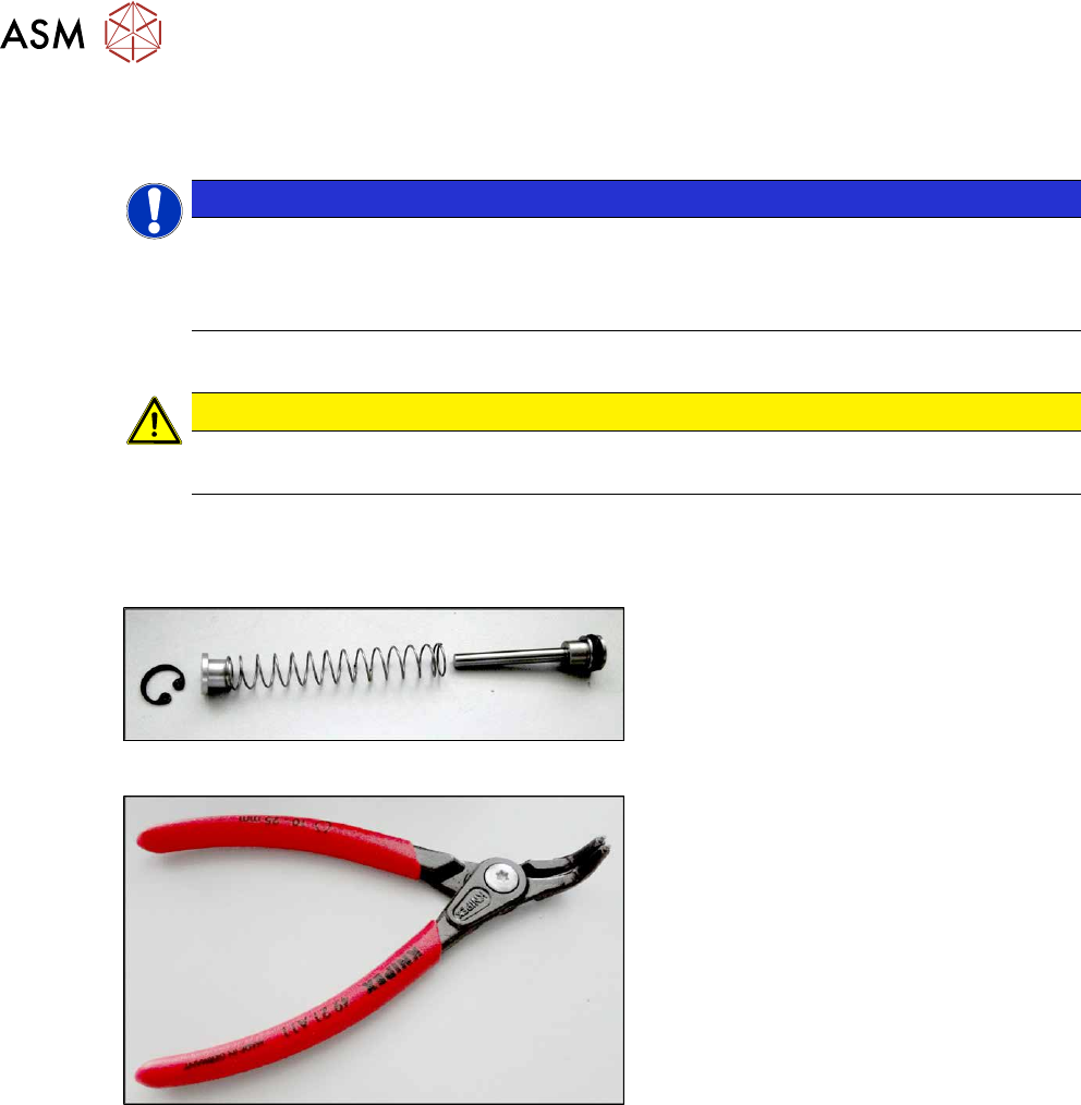
Fig.447: ETP feeder unlock device
●
SPP feeder unlock device [03088220-
xx]
Fig.448: Inside circlip pliers, bent tips J01
●
Inside circlip pliers, bent tips J01
[00365186‑xx]
●
Snipe nose pliers [00353833-xx]
9 Component feeding
9.2 COT insert
Service Manual SIPLACE X-Series S (from Hxxxx) 01/2021 319
Removal
► Dismantle the feeder unlock device (see 9.2.5 "Replacing the 40-fold feeder unlock
device" [}317]).
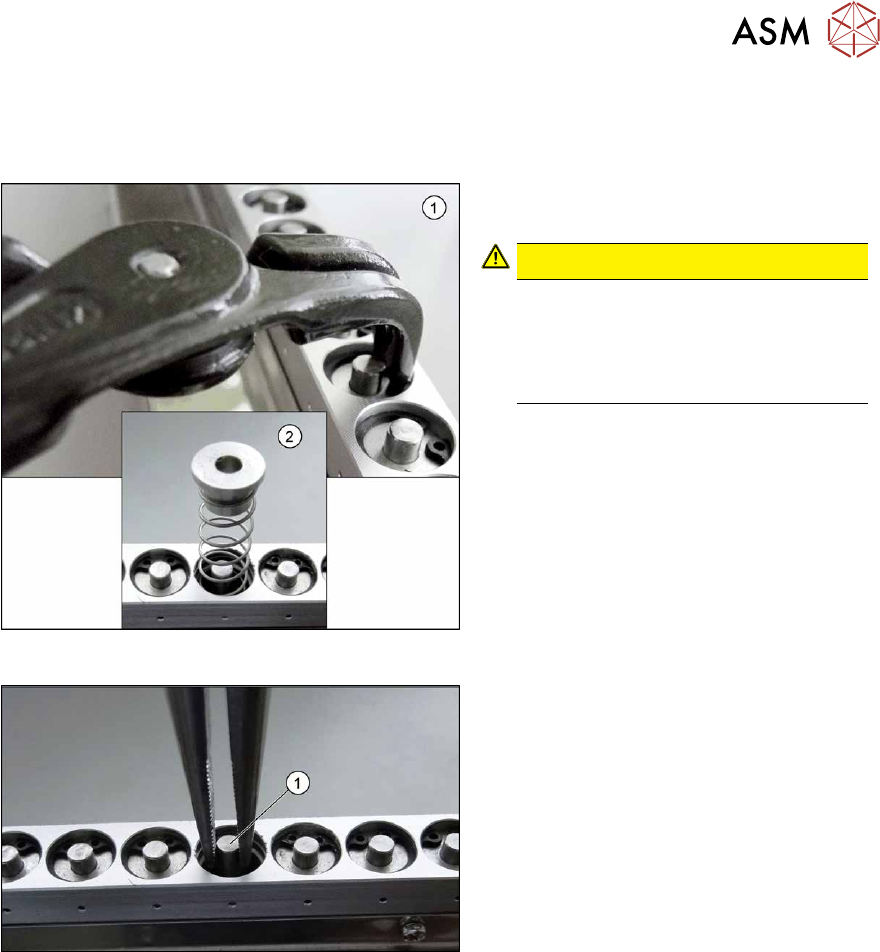
Fig.449: Circlip
► Use the inside circlip pliers to remove
the circlip.
CAUTION!
Spring
Under the circlip you will find a spring
(2)
. Make sure that the circlip and the
upper guidance bushing do not blow
away and get lost.
.
Fig.450: Snipe pliers
► Use the snipe pliers to remove the un-
locking pin.
Installation
Follow the removal instructions in reverse order for installation. Observe the following note:
► Pay attention to the spring during insertion.
9 Component feeding
9.2 COT insert
320 Service Manual SIPLACE X-Series S (from Hxxxx) 01/2021
9.2.7 Replacing the safety switch
Parts, equipment and tools
●
Safety switch [03019065-xx]
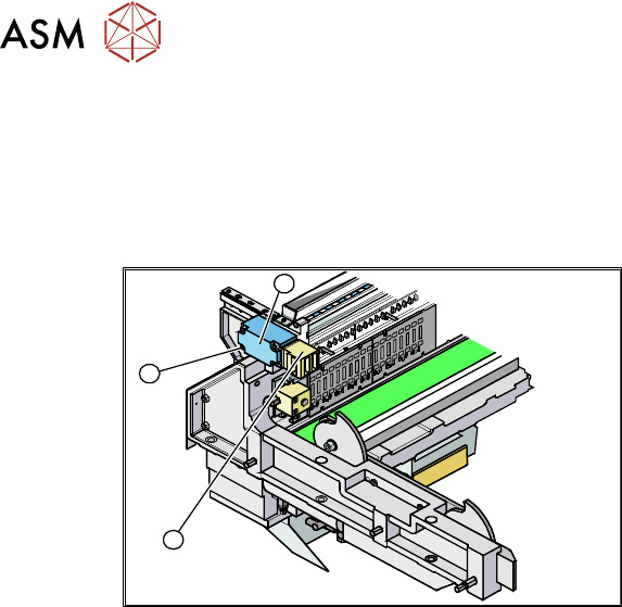
Overview
3
2
1
Fig.451: Safety switch
1. Safety switch
2. Four fixing screws
3. Contact jack
Removal
► Switch off the machine, disconnect it from the power supply and secure it to prevent
unauthorized reactivation.
1.2 "Preparatory work..." [}16]
► Depending on the options installed, you may need to loosen the COT insert and pull it slightly
forwards for better access. For more information about this, read section 9.2.3
"Replacing the
COT Insert Assembly" [}313].
► Dismantle the nozzle changer for better access.
► Remove the screws fastening the safety switch.
► Unthread the connection cable up to the connectors down in the machine frame and to the
feed control and then unplug it. Dismantle the two cover plates at the back of the COT insert.
Installation
► Installation is performed by following the above instructions in the reverse order. Also observe
the following instructions:
– Move the component trolley into the COT insert and check whether the component trolley
can be moved into the contact jack. Correct the position of the safety switch, where neces-
sary.