00198829-01_SM_X-Series-S_Hxxxx_EN.pdf - 第205页
7 Conveyor 7.6 Conveyor Belt, Belt Drive and Hexagonal Shaft Service Manual SIPLACE X-Series S (from Hxxxx) 01/2021 205 NOTICE Replacing a movable idler pulley The idlers are fitted onto a clamping device [00360422-xx]. …
7 Conveyor
7.6 Conveyor Belt, Belt Drive and Hexagonal Shaft
204 Service Manual SIPLACE X-Series S (from Hxxxx) 01/2021
7.6.5 Replacing the idler pulley
Parts, equipment and tools
●
Idler pulley SXa [03092899Sxx] (including screws, spacer and clamping device)
●
Magnet lifter, if needed or tweezers and adhesive tape
●
Torx screwdriver ESD 1.0-5.0 Nm [03078400-xx]
●
Bit holder for TorqueVario screwdriver [03078706-xx]
●
Bit, size 4
●
Measuring scale, if needed
Overview
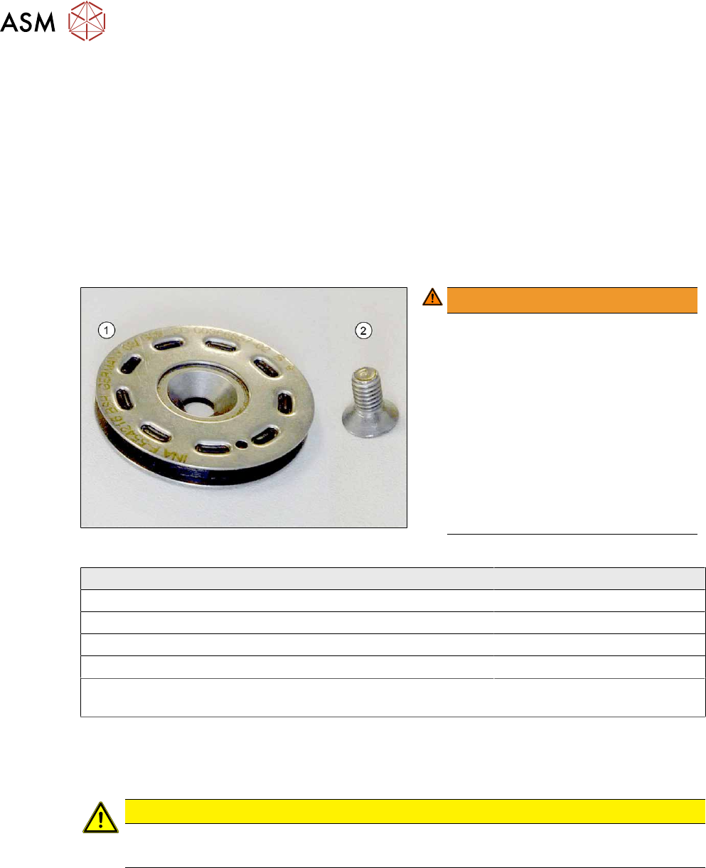
Fig.268: Idler pulley with fastening screw
WARNING!
Tighten the screws(1) fastening the
idler pulleys(2)
with 1.8Nm. Make
sure that you do not tighten the screws
too much. This could cause irreparable
damage to the conveyor!
The corresponding threads are only in
1.5 to 2mm thick plates and could be
damaged if you use a torque which is
too high. For this reason, avoid using
screws which are too short. Use a
measuring scale to check, if needed!
This could cause irreparable damage
to the conveyor!
.
Installation location of idler pulley Fastening screw
Placement area ISO10642 - M4x6
Movable idler pulleys ISO10642 - M4x8
Other positions in the input, intermediate and output area ISO10642 - M4x10
Exception: conveyor side A next to the LLS transmitter ISO10642 - M4x8
First and last idler pulley on the transfer positions to the prede-
cessor and successor machine
One additional spacer disk
For an overview of the individual movable idler pulleys on the conveyor sides, see section 7.6.2.1
"Setting the Tension of the Conveyor Toothed Belt" [}200].
Removal
CAUTION
Toothed belt
► Make sure that the toothed belt is not folded or otherwise damaged.
► Use the software to move the conveyor sides into a position which allows you best access. As
an alternative, you can loosen the clamps for the relevant sides in dual conveyors.
7.2 "Loosening the Conveyor Side Clamps" [}162]
► Switch off the machine, disconnect it from the power supply and secure it to prevent
unauthorized reactivation.
1.2 "Preparatory work..." [}16]
► Loosen the movable idler pulley.
7 Conveyor
7.6 Conveyor Belt, Belt Drive and Hexagonal Shaft
Service Manual SIPLACE X-Series S (from Hxxxx) 01/2021 205
NOTICE
Replacing a movable idler pulley
The idlers are fitted onto a clamping device [00360422-xx]. When you fit the new movable
idler pulley, this clamping device needs to be pushed towards the movable idler pulley. You
therefore need to perform the following additional steps when replacing a movable idler pul-
ley:
► Dismantle the clamping or guide rail via the movable idler pulley.
Secure the clamping piece in the conveyor side with adhesive tape. The lack of room
means that subsequent insertion and fixture involves much time and work.
► Remove the fastening screw on the idler pulley to be replaced.
CAUTION
Spacer, spacer disk
The fastening screw for some idler pulleys also holds the spacers or spacer disks in place.
► Make sure that you do not loose these.
► Unthread the idler pulley from the conveyor toothed belt and remove it.
Installation
Follow the removal instructions in reverse order for installation. Also observe the following instruc-
tions:
► Make sure you use the correct fastening screw.
Tighten this fastening screw with a torque of 1.8Nm
. Make sure that you do not tighten the
screws too much. This could cause irreparable damage to the conveyor!
► Use any spacer disks or spacers available.
► Make sure that you do not fold or otherwise damage the toothed belt.
► Make sure that the toothed belt is positioned accurately in the guidance on the motor shaft/in
the belt drive.
► Remove the adhesive tape, if necessary.
► While you tighten the movable idler pulley, set the tension of the toothed belt correctly
7.6.2 "Setting the belt tension (conveyor belt)" [}200]
7.6.6 Replacing the hexagonal shaft
Parts, equipment and tools
●
Hexagonal shaft SX14 [03094721-xx]
●
Bearing for hexagonal shaft SXa (plastic bearing) – pack of 10 [03092024-xx]
●
Adhesive tape
Removal
CAUTION
Do not damage the hexagonal shafts
Make sure that you do not damage the hexagonal shafts. If you do, this will impair the width
adjustment.
► Damaged hexagonal shafts must be replaced.
► Use the software to move the conveyor sides into a position which allows you best access. As
an alternative, you can loosen the clamps for the relevant sides in dual conveyors.
7.2 "Loosening the Conveyor Side Clamps" [}162]
► Switch off the machine, disconnect it from the power supply and secure it to prevent
unauthorized reactivation.
1.2 "Preparatory work..." [}16]
7 Conveyor
7.6 Conveyor Belt, Belt Drive and Hexagonal Shaft
206 Service Manual SIPLACE X-Series S (from Hxxxx) 01/2021
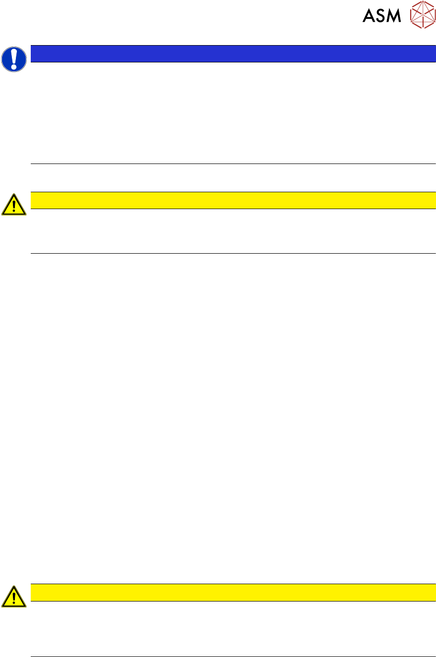
Fig.269: Hexagonal shaft mount
The hexagonal shafts (1) are fixed on both
sides of the conveyor with brackets. When
you dismantle the hexagonal shaft, you only
need to take off one of these brackets.
► Remove the screws (4) fastening the
hexagonal shaft mount (2)
(Allen key 3)
and remove the plastic bearings (3)
on
both sides of the conveyor.
CAUTION
Plastic bearing
Make sure that you do not lose the plastic bearings when dismantling the bracket. When
you dismantle a bracket, always remove all the plastic bearings on this bracket and the op-
posite bracket. These would otherwise obstruct the movement of the hexagonal shafts and
could easily fall out.
► In order to prevent a plastic bearing from falling out and to make subsequent fitting
easier, these can be fixed in place with adhesive tape.
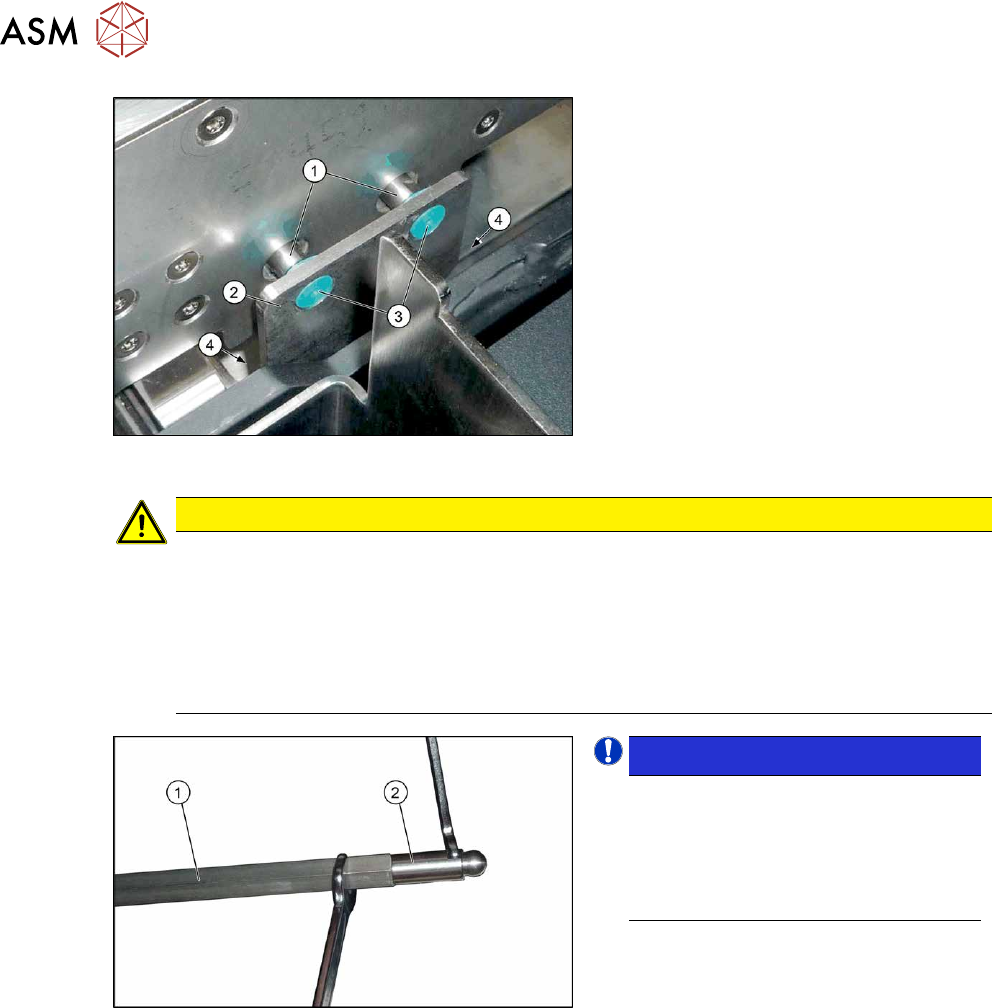
Fig.270: Ball studs on the hexagonal shafts
NOTICE!
Many tasks on the conveyor require
you to simply move the hexagonal
shafts instead of removing them. In
these cases, you generally do not
need to dismantle the ball studs on the
ends of the hexagonal shafts.
.
► Unscrew the two ball studs (2) from the
two ends of the hexagonal shaft (1)
(fork wrench size 8 and10). This
shortens the shaft and makes it easier
to handle.
► Unthread the hexagonal shaft.
Installation
Follow the removal instructions in reverse order for installation. Also observe the following instruc-
tions:
► Once you have loosened the ball studs of the hexagonal shafts, tighten these with a torque of
14 Nm.
► Make sure that the hexagonal shafts are not damaged by the tool.
► Do not tighten the screws fastening the hexagonal shaft holder too much yet.
► Check whether the tape drive and the drive unit are aligned correctly to one another.
To do this, push the conveyor sides together until you can still just reach the fastening screws.
Check the conveyor drive for ease of movement by turning the hexagonal shaft. You may
need to loosen the conveyor drive again and then reset it.