00198829-01_SM_X-Series-S_Hxxxx_EN.pdf - 第182页
7 Conveyor 7.5 Width Adjustment, Clamps and Cylinder Unit 182 Service Manual SIPLACE X-Series S (from Hxxxx) 01/2021 7.5.2 Replacing the drive (width adjustment) Parts, equipment and tools ● Drive unit of width adjustmen…
7 Conveyor
7.5 Width Adjustment, Clamps and Cylinder Unit
Service Manual SIPLACE X-Series S (from Hxxxx) 01/2021 181
7.5 Width Adjustment, Clamps and Cylinder Unit
NOTICE
Exemplary description
Provided identical parts are present, the width adjustment will be described using the exam-
ple of a dual conveyor.
The procedure is the same for a single conveyor.
Any relevant differences will be mentioned explicitly.
7.5.1 Overview of width adjustment
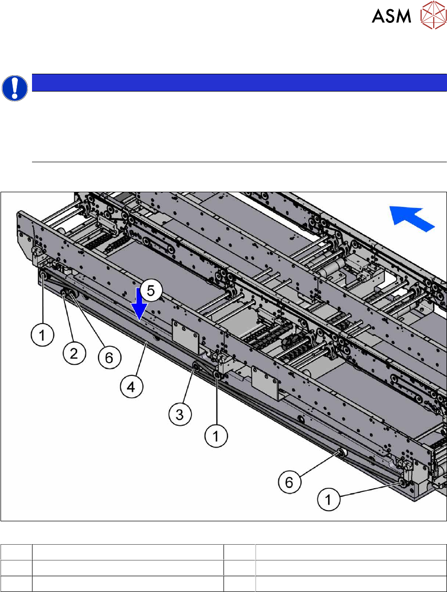
Fig.236: Overview of width adjustment
1 Cylinder units 2 Width adjustment drive
3 Movable idler pulley 4 Toothed belt of width adjustment
5 Measurement point for belt tension 6 Idler pulley
7 Conveyor
7.5 Width Adjustment, Clamps and Cylinder Unit
182 Service Manual SIPLACE X-Series S (from Hxxxx) 01/2021
7.5.2 Replacing the drive (width adjustment)
Parts, equipment and tools
●
Drive unit of width adjustment assembly SXa [03092543-xx]
●
If needed, bearing for hexagonal shaft SXa (plastic bearing) – pack of 10 [03092024-xx]
Overview
See 7.5.1 "Overview of width adjustment" [}181]
Removal
► Use the software to move the conveyor sides into a position which allows you best access. As
an alternative, you can loosen the clamps for the relevant sides in dual conveyors.
7.2 "Loosening the Conveyor Side Clamps" [}162]
► Switch off the machine, disconnect it from the power supply and secure it to prevent
unauthorized reactivation.
1.2 "Preparatory work..." [}16]
► Move the cylinder units as far as the end stop on one side of the conveyor. To do this, move
the toothed belt of the width adjustment.
► Dismantle the lifting table plate over the width adjustment drive.
7.3.1 "Replacing the lifting table plate" [}167]
► Dismantle the cover over the conveyor control at the movable idler pulley.
► Loosen the movable idler pulleyfor the width adjustment toothed belt (SW10).
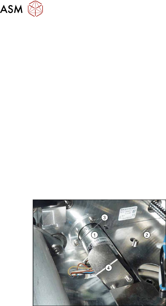
Fig.237: Removing the width adjustment drive
► Dismantle the cover plate(2) next to
the width adjustment drive (1)
.
► Remove the screws(3) fastening the
width adjustment drive.
► Remove the screws fastening the cover
plate(4)
over the connectors of the
width adjustment drive.
► Unplug the connector from the width adjustment drive. You may want to mark the position, to
make clear assignment easier later on.
Installation
Follow the removal instructions in reverse order for installation. Also observe the following instruc-
tions:
► Carefully thread in the toothed belt. To do this, carefully lift the toothed belt a little ( e.g. with
the shorter end of an Allen key).
► Make sure that the cylinder units are parallel.
7.10.2 "Setting the Parallelism of the Conveyor Sides and Adjustment Units" [}248]
► Set the correct belt tension.
7.5.3.1 "Setting the belt tension (width adjustment)" [}183]

7 Conveyor
7.5 Width Adjustment, Clamps and Cylinder Unit
Service Manual SIPLACE X-Series S (from Hxxxx) 01/2021 183
7.5.3 Replacing the toothed belt (width adjustment)
Parts, equipment and tools
●
Toothed belt BRECOFLEX 12 T5/3950 [03087325-xx]
●
Bearing for hexagonal shaft SXa (plastic bearing) – pack of 10 [03092024-xx]
Overview
See 7.5.1 "Overview of width adjustment" [}181]
Removal
► Use the software to move the conveyor sides into a position which allows you best access. As
an alternative, you can loosen the clamps for the relevant sides in dual conveyors.
7.2 "Loosening the Conveyor Side Clamps" [}162]
► Switch off the machine, disconnect it from the power supply and secure it to prevent
unauthorized reactivation.
1.2 "Preparatory work..." [}16]
► Move the cylinder units as far as the end stop on one side of the conveyor. To do this, move
the toothed belt of the width adjustment.
► Dismantle the cover over the conveyor control.
► Loosen the movable idler pulleyfor the width adjustment toothed belt on the inside of the con-
veyor. (Open-ended wrench, size 10)
► Unthread the toothed belt.
Installation
Follow the removal instructions in reverse order for installation. Also observe the following instruc-
tions:
► Carefully thread in the toothed belt. To do this, carefully lift the toothed belt a little ( e.g. with
the shorter end of an Allen key).
► Make sure that the cylinder units are parallel.
Setting the Parallelism of the Conveyor Sides
► Set the correct belt tension (see below).
7.5.3.1 Setting the belt tension (width adjustment)
► Use the software to move the conveyor sides into a position which allows you best access. As
an alternative, you can loosen the clamps for the relevant sides in dual conveyors.
7.2 "Loosening the Conveyor Side Clamps" [}162]
► Switch off the machine, disconnect it from the power supply and secure it to prevent
unauthorized reactivation.
1.2 "Preparatory work..." [}16]
► Check the tension at the center between the two upper idler pulleys. The tension must be 25
to 27Hz.
► If the tension is not correct, loosen the screw fastening the movable idler pulley and correct
the tension. You may have to dismantle the cover over the conveyor control.
► Repeat the measurement 4 times.