00198829-01_SM_X-Series-S_Hxxxx_EN.pdf - 第335页
9 Component feeding 9.3 X-Series Component Trolley Service Manual SIPLACE X-Series S (from Hxxxx) 01/2021 335 9.3.6 Replacing the insert feeder Parts, equipment and tools Select the right insert feeder: Fig.472: Insert …
9 Component feeding
9.3 X-Series Component Trolley
334 Service Manual SIPLACE X-Series S (from Hxxxx) 01/2021
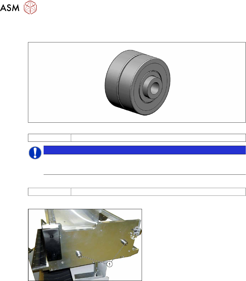
9.3.5 Replacing the bearing assembly
Parts
Fig.470: Bearing assembly
03103947-xx Bearing assembly
NOTICE
Replacing all sleeves
We recommend that you always replace all bearing assemblies belonging to a changeover
table at the same time.
Tools
00334892-xx Loctite 243
Overview
Fig.471: Centering sleeves
1. Bearing assembly (four per table)
Removal
► Remove the screw fastening the bearing assembly and then remove the bearing assembly.
Installation
Follow the removal instructions in reverse order for installation. Also observe the following instruc-
tions:
► Secure the screw with Loctite243.
9 Component feeding
9.3 X-Series Component Trolley
Service Manual SIPLACE X-Series S (from Hxxxx) 01/2021 335
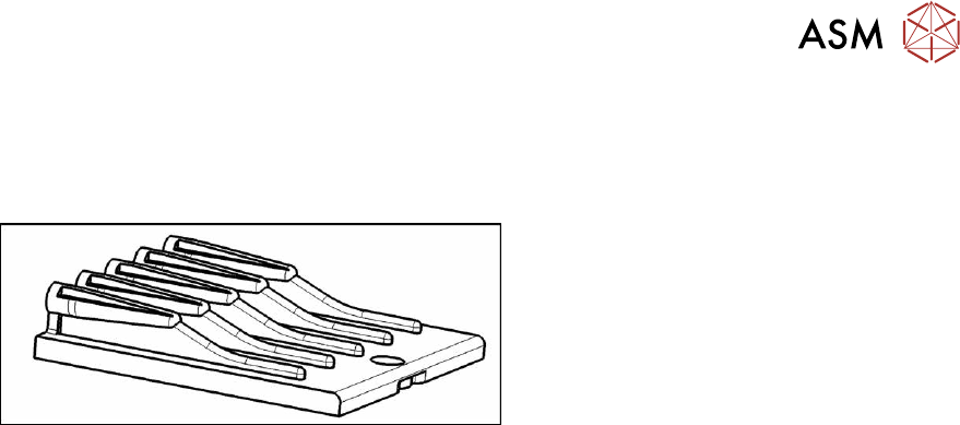
9.3.6 Replacing the insert feeder
Parts, equipment and tools
Select the right insert feeder:
Fig.472: Insert feeder [03002898-xx]
Insert feeder [03002898-xx]
Suitable for:
●
SIPLACE X-series component trolley
●
Component trolley SIPLACE SX1/SX2
(30 or 60 tracks)
●
Manual table SIPLACE X‑SeriesS
Removal
► Move the component trolley out of the machine.
► Remove the screw fastening the guide profile and then remove the guide profile.
Installation
Follow the removal instructions in reverse order for installation. Observe the following note:
► Make sure that the insert is aligned properly with the guidance behind it. You must be able to
push feeder modules into the feeder location without edge interference.
9 Component feeding
9.3 X-Series Component Trolley
336 Service Manual SIPLACE X-Series S (from Hxxxx) 01/2021
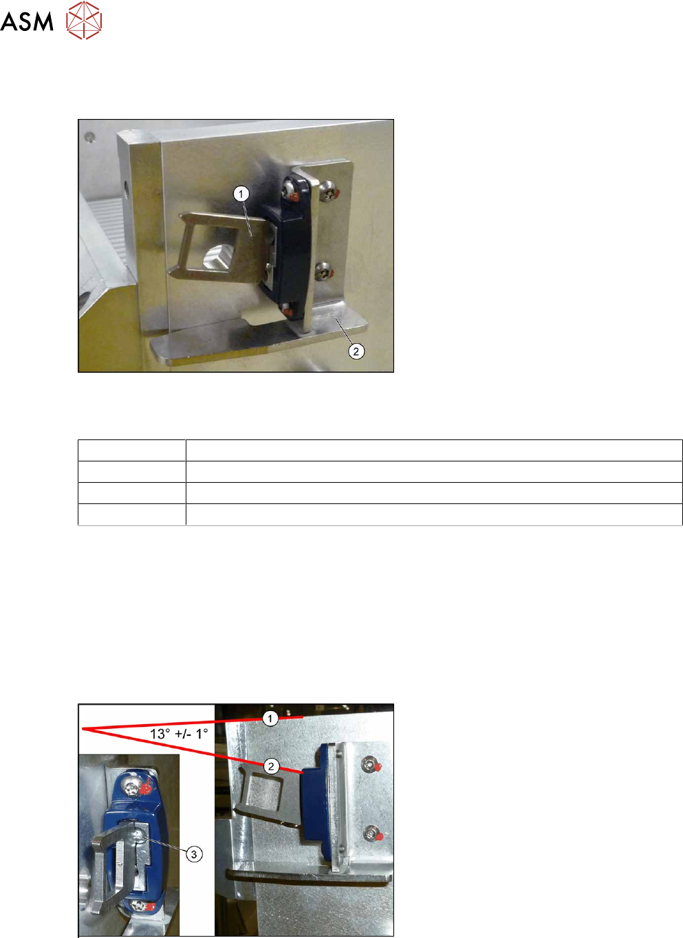
9.3.7 Replacing the Actuator/Protective Bracket
Parts
Fig.473: Actuator
1. Actuator AZ335 Schmersal
[03013488‑xx]
2. Protective bracket: holder and protec-
tion for actuator [03095447-xx]
Equipment and tools
00376503-xx Set of Torx offset screwdrivers with spherical heads
03148413-xx Bit 1/4, TX20 with drilled hole (for screw ISO 7380-TX with pin - M4)
00353832-xx Allen key set
00334892‑xx Loctite 243
Removal
► Remove the two screwsfastening the actuator/protective bracket and then remove the actu-
ator/protective bracket.
Installation
Follow the removal instructions in reverse order for installation. Also observe the following instruc-
tions:
► Fix the actuator with two fastening screws to the protective bracket (torque 2.0Nm, Loctite
243).
Fig.474: Setting the actuator
► Set the actuator with the help of the ad-
justment screw (3)
.
Between the upper edge(1)
of the
table and the actuator(2)
you need to
set an angle of 13°+/‑1°
.
The actuator must be able to slide into
the safety switch without rubbing
against the plastic.