00198829-01_SM_X-Series-S_Hxxxx_EN.pdf - 第277页
8 Head exchange 8.8 Replacing the SIPLACE Twin Service Manual SIPLACE X-Series S (from Hxxxx) 01/2021 277 ► Placing the head into the head transport box ► If you need to perform further work on this placement head (e.g. …
8 Head exchange
8.8 Replacing the SIPLACE Twin
276 Service Manual SIPLACE X-Series S (from Hxxxx) 01/2021
Removal
► Switch off the machine, disconnect it from the power supply and secure it to prevent
unauthorized reactivation.
1.2 "Preparatory work..." [}16]
► Switch off the compressed air supply
5.2 "Disabling the compressed air supply" [}86]
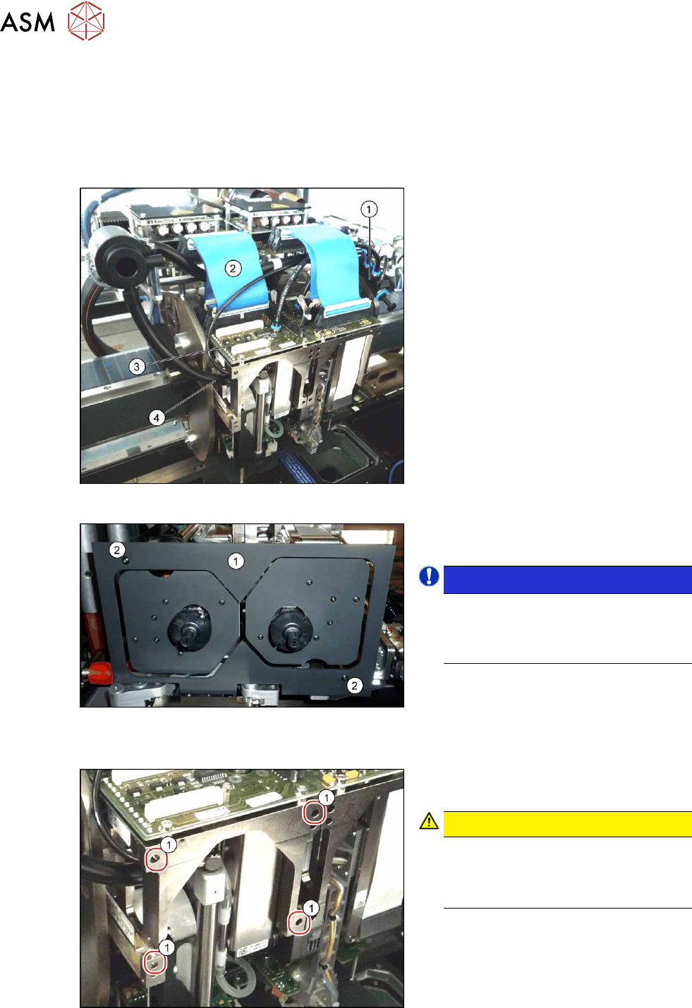
Fig.370: Connections (example of SIPLACE SX1 shown)
► Move the gantry into a position which
allows you best access.
► Unplug the pneumatic connection from
the Twin vacuum generator to the
pneumatic distributor(1)
and from the
silencer.
► Disconnect the exhaust air silicone
hose from the Twin vacuum generator
(4)
.
► Unplug the pneumatic connection from
the pneumatic distributor(1)
to the
Twin return cylinder.
► Unplug the flat ribbon cable(2) from
the head main board(3)
on the Twin.
Fig.371: Camera lens hood
► Remove the camera screen(1). This is
fastened with two black screws(2)
.
NOTICE!
Only use these black screws to fix the
camera lens hood. This prevents re-
flection when measuring components
with the stationary camera.
.
Each module is fixed with four screws (TX20) to the head plate and is positioned with two pins.
Fig.372: Fastening screws
► Unscrew the first three fastening
screws.
CAUTION!
Hold tight!
Hold the module tight before removing
the last of the four screws. The module
could otherwise fall down.
.
► Unscrew the fourth fastening screw and
pull the module out of the pins.

8 Head exchange
8.8 Replacing the SIPLACE Twin
Service Manual SIPLACE X-Series S (from Hxxxx) 01/2021 277
► Placing the head into the head transport box
► If you need to perform further work on this placement head (e.g. replacing spare parts), fit the
placement head to the head mount [03056231-xx].
Installation
Follow the removal instructions in reverse order for installation. Also observe the following instruc-
tions:
► Fit the fastening screws on the other side of the module, if needed (see above).
► Make a note of the force values for the new module. These force values can be found on a
label at the side of the module.
► Make sure that the assembly position is correct.
► Perform a head calibration.
See also
2 8.9 "Installation Positions on the Head Plate" [}278]
2 8.10 "Calibration" [}279]
8 Head exchange
8.9 Installation Positions on the Head Plate
278 Service Manual SIPLACE X-Series S (from Hxxxx) 01/2021
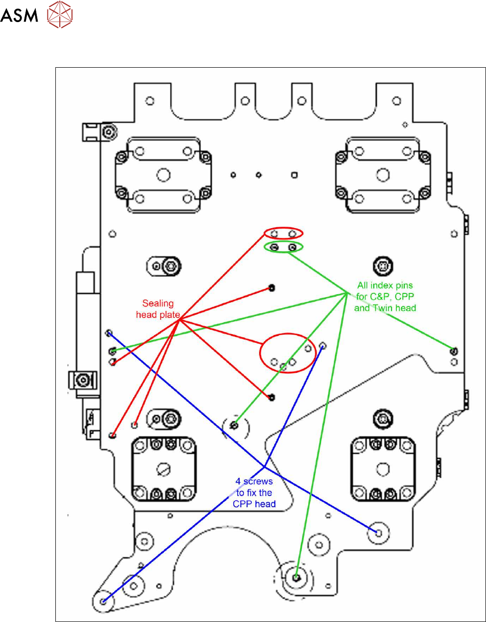
8.9 Installation Positions on the Head Plate
Fig.373: Installation positions on the head plate