00198829-01_SM_X-Series-S_Hxxxx_EN.pdf - 第226页
7 Conveyor 7.8 Laser light barriers, fiber optic cable and PCB sensors 226 Service Manual SIPLACE X-Series S (from Hxxxx) 01/2021 Setting with the adjusting gauge Fig.300: Focusing the laser beam (example of X-Series sh…
7 Conveyor
7.8 Laser light barriers, fiber optic cable and PCB sensors
Service Manual SIPLACE X-Series S (from Hxxxx) 01/2021 225
7.8.4 Correcting the Laser Light Barrier Setting
DANGER
Laser class 2
The laser light barrier transmitter emits class 2 laser beams. You therefore do not require
additional protective measures!
► However, you should never look into the laser beam!
► Adjust the laser beam only from the rear side of the laser!
Equipment and tools
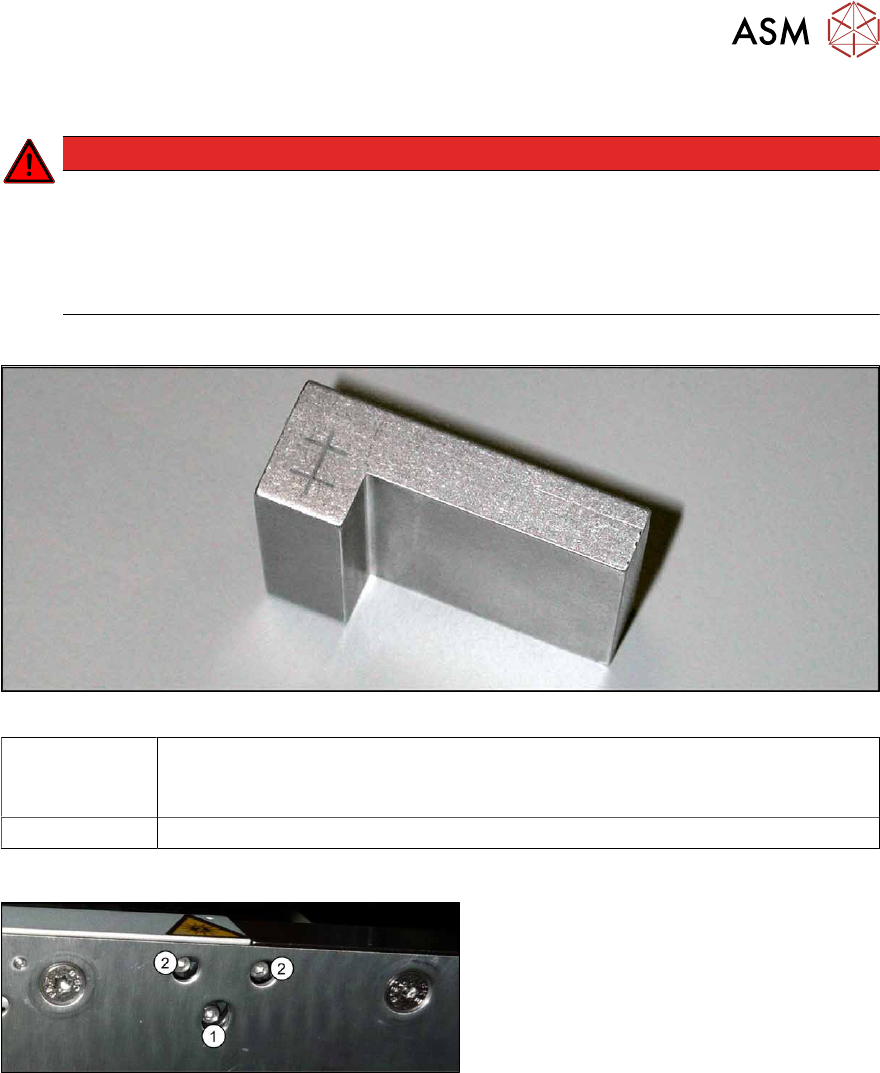
Fig.298: Setting gauge
00369205-xx Adjusting gauge "Adjustment of laser, PCB conveyor"
Semi-transparent paper or plastic laminate can be used as an alternative, for
better recognition of the laser beam.
00353832-xx Allen key set
Overview
Fig.299: Laser transmitter
The fastening screw(1) is tightened by
hand.
The adjustment screws(2) might not be fully
tightened, depending on the setting.
Preparation
► Set the conveyor to the maximum width, to maximize any potential deviation of the laser
beam.
► Select Enable safety mode in software.
► Activate the relevant laser diode using the input/output functions in the station software.
7 Conveyor
7.8 Laser light barriers, fiber optic cable and PCB sensors
226 Service Manual SIPLACE X-Series S (from Hxxxx) 01/2021
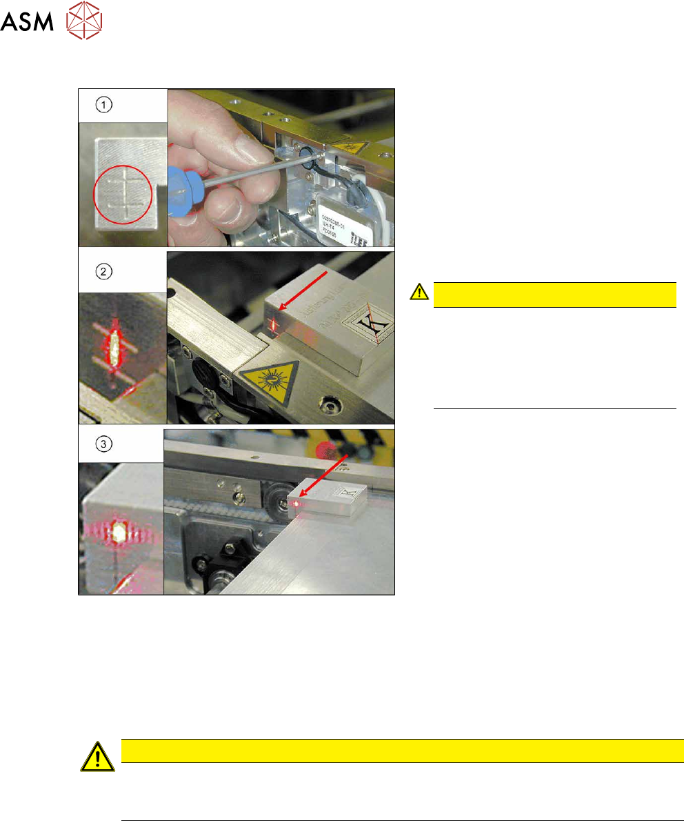
Setting with the adjusting gauge
Fig.300: Focusing the laser beam (example of X-Series
shown)
1. Setting the laser light barrier
2. Minimum width
3. Maximum width
► Check the path of the laser beam at
maximum width (3)
with the help of the
adjusting gauge.
► With the help of the three setting
screws, adjust the laser beam to the
center of the gauge cross (1)
.
CAUTION!
Screws on the laser transmitter
Hand-tighten the lower screw. The top
two screws are used to set the laser
beam. These may not be fully
tightened. Otherwise the laser trans-
mitter could be damaged.
.
► Check the setting at minimum width(2).
► Check the PCB reference corner and
reteach, if necessary.
Setting without adjusting gauge
► Check the path of the laser beam with the help of the semi-transparent paper or the laminate.
► Use the top two screws to set the laser beam so that it is correctly aligned with the laser recei-
ver.
CAUTION
Screws on the laser transmitter
► Hand-tighten the lower screw. The top two screws are used to set the laser beam.
These may not be fully tightened. Otherwise the laser transmitter could be damaged.
► Now position the conveyor to minimum width and check the setting.
► Check the PCB reference corner and reteach, if necessary.
7 Conveyor
7.8 Laser light barriers, fiber optic cable and PCB sensors
Service Manual SIPLACE X-Series S (from Hxxxx) 01/2021 227
7.8.5 Replacing the fiber optic cable
NOTICE
Repairing the fiber optic cable
Depending on the machine and the installation position, the complete replacement of the
fiber optic cable may take approx. 2 to 2.5 hours. To avoid downtimes, it is possible to per-
form a short-term repair using the repair hose. Observe the instructions in section 7.8.6
"Repairing the fiber optic cables" [}230].
Parts, equipment and tools
●
Fiber optic cable LL3-TV05 3 m [03092408-xx]
(two fiber optic cables per pack incl. cutter tool)
NOTICE
Transmitter/receiver
Both fiber optic cables are technically identical and be used either as transmitters or receiv-
ers.
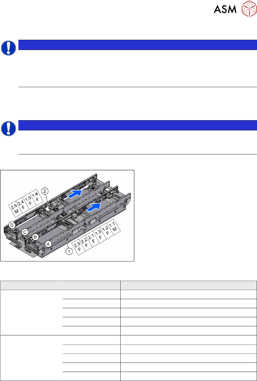
Overview
Fig.301: Overview of fiber optic cable sensor
The fiber optic cable sensors are located at
locations 1 and 4, under the covers of the
conveyor control(1)
and(2).
The sensors for the input conveyor, place-
ment area 1 and intermediate conveyor can
be found at (1)
.
The sensors for placement area 2 and the
output conveyor can be found at (2)
.
The fiber optic cable sensors are separated
into master (M) and slave (F).
The receiver is always at the top of the
sensors and the transmitter at the bottom.
The transmitters are located on sides B and
D.
The receivers are located on sides A and C.
Conveyor lane Designation Area
Lane 1 1.1 Input belt
1.2 Placement area 1
1.3 Intermediate belt
1.4 Placement area 2
1.5 Output belt
Lane 2 2.1 Input belt
2.2 Placement area 1
2.3 Intermediate belt
2.4 Placement area 2
2.5 Output belt