00198829-01_SM_X-Series-S_Hxxxx_EN.pdf - 第216页
7 Conveyor 7.8 Laser light barriers, fiber optic cable and PCB sensors 216 Service Manual SIPLACE X-Series S (from Hxxxx) 01/2021 7.8 Laser light barriers, fiber optic cable and PCB sensors 7.8.1 Replacing the Laser Ligh…
7 Conveyor
7.7 Clamping Plate, Clamping Rails and Belt Guidance
Service Manual SIPLACE X-Series S (from Hxxxx) 01/2021 215
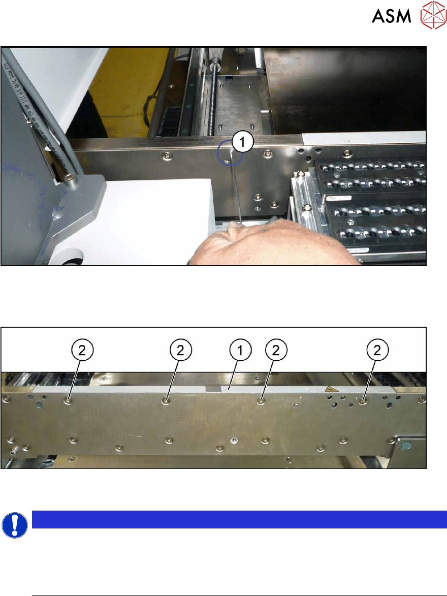
Fig.279: Fiber optic cable transmitter/receiver
► If a fiber optic cable receiver or transmitter is fitted to the rail:
the receiver/transmitter is fixed from the outside to the side wall with a grub screw(1)
. In order
to remove the rail, you need to loosen this grub screw.
Fig.280: Fastening screws (example of clamping rail shown)
► Remove the screws(2) fastening the rail (1) (three or four screws, depending on the position).
NOTICE
Special screws
These are special screws with a length of 14.7 mm.
In some cases, one of the screws may be slightly shorter. In this case, make a note of the
positions, to make clear assignment easier later on. If incorrectly used, you might not be
able to move the clamping plate when it is installed.
► Carefully pull the clamping rail up and off the conveyor side.
► You may need to dismantle the transmitter/receiver fixed to the clamping rail.
Installation
Follow the removal instructions in reverse order for installation. Also observe the following instructions:
► Tighten the rail fastening screws with a torque of 6 Nm. Do not tighten too much. This could
damage the thread or distort the conveyor side.
► Check the setting for the transmitter/receiver and correct if necessary.
7.8.3 "Checking the laser light barrier" [}222]
7.8.4 "Correcting the Laser Light Barrier Setting" [}225]
► Once you have loosened the conveyor belt, set the tension again.
7.6.2 "Setting the belt tension (conveyor belt)" [}200]
7 Conveyor
7.8 Laser light barriers, fiber optic cable and PCB sensors
216 Service Manual SIPLACE X-Series S (from Hxxxx) 01/2021
7.8 Laser light barriers, fiber optic cable and PCB sensors
7.8.1 Replacing the Laser Light Barrier for the Transmitter/Receiver
Parts, equipment and tools
NOTICE
Old and new version of transmitter and receiver
There are old and new versions of the transmitter and receiver modules.
Old: [03092578-xx], [03091492-xx]
New: [03109439‑xx] (contains: 03098280-xx, 03098281-xx)
► The old version can be replaced with the new one.
► The transmitter and receiver of the new version are coordinated with one an-
other and must always be replaced together. It is not possible to just replace the
transmitter or receiver alone.
► In the old version, the connection cable is fixed to the module.
In the new version, the connection cable has a plug at each end. In this case, the con-
nection cable needs to be connected to the module before it is fitted.
●
Light barrier transmitter and receiver SX1V2 / X‑SeriesS [03109439‑xx] (replaces:
03092578‑xx, 03091492‑xx)
●
Flashlight, if needed
●
Magnet lifter, if needed
●
Tweezers, if needed
●
If needed, semi-transparent paper or plastic (for better recognition of the laser beam)
Overview
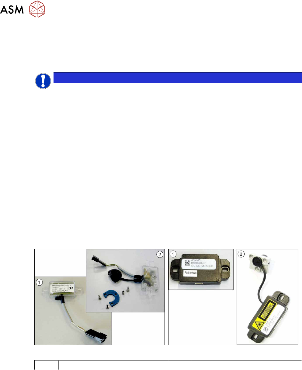
Fig.281: Receiver and transmitter (old version)
Fig.282: Receiver and transmitter (new version)
1 Receiver 2 Transmitter
7 Conveyor
7.8 Laser light barriers, fiber optic cable and PCB sensors
Service Manual SIPLACE X-Series S (from Hxxxx) 01/2021 217
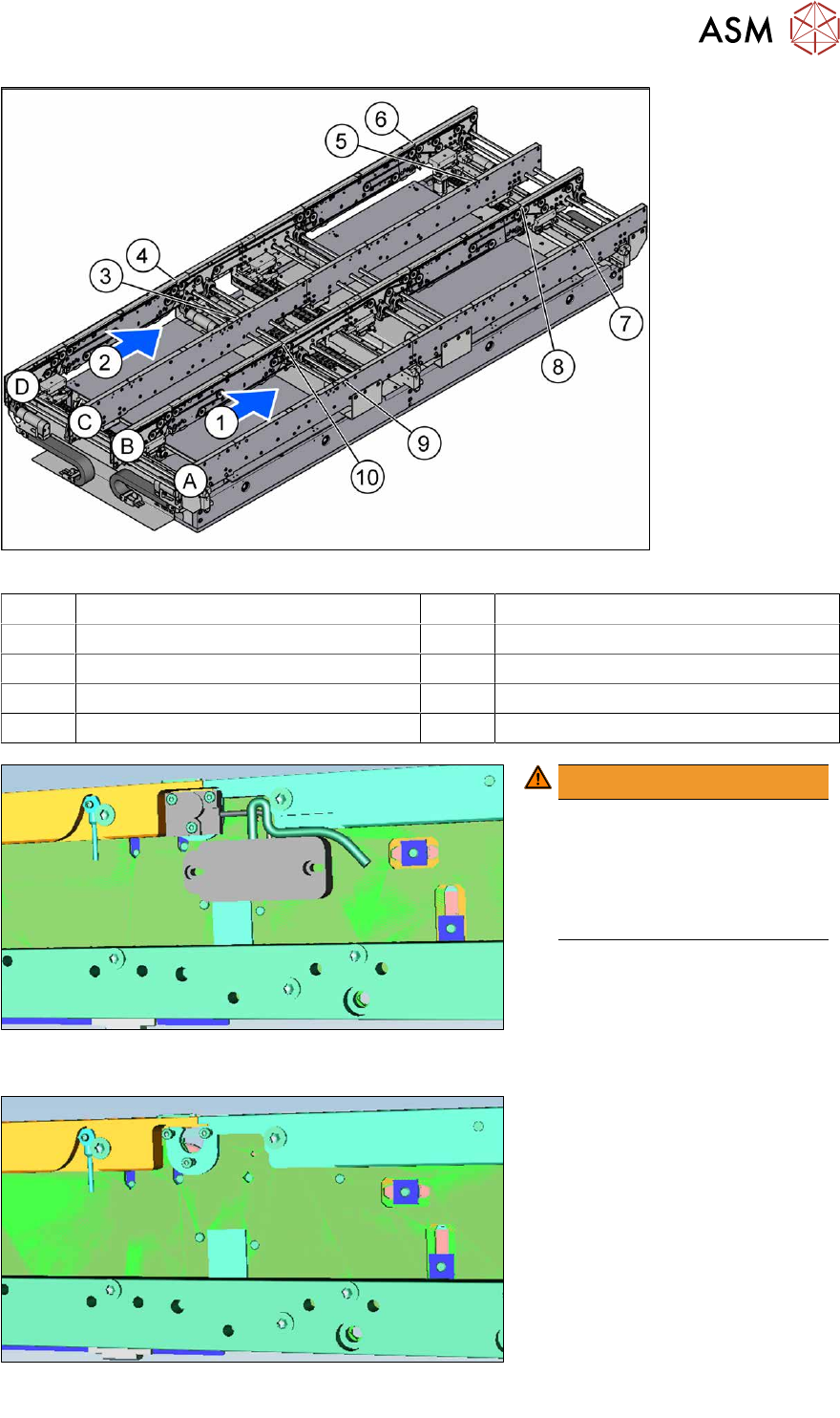
Fig.283: Overview of laser light barriers
A to D Conveyor side A to D 1, 2 Conveyor lane 1, conveyor lane 2
3 Transmitter PA1 side C 4 Receiver PA1 side D
5 Transmitter PA2 side C 6 Receiver PA2 side D
7 Transmitter PA2 side A 8 Receiver PA2 side B
9 Transmitter PA1 side A 10 Receiver PA1 side B
Fig.284: Laser light barrier with electronics (example of input con-
veyor used)
WARNING!
Do not dismantle the cover
plate!
The cover plate has been hid-
den for greater clarity in these
diagrams. Never dismantle the
cover plate!
.
Fig.285: Laser light barrier without electronics (example of input con-
veyor used)