00198829-01_SM_X-Series-S_Hxxxx_EN.pdf - 第39页
2 Basic Machine 2.8 Nozzle Changers and Reject Boxes Service Manual SIPLACE X-Series S (from Hxxxx) 01/2021 39 Fig.33: Sensors for reject bin SIPLACE X-Series S with JTF Fig.34: Sensors for reject bin SIPLACE X-Series …
2 Basic Machine
2.8 Nozzle Changers and Reject Boxes
38 Service Manual SIPLACE X-Series S (from Hxxxx) 01/2021
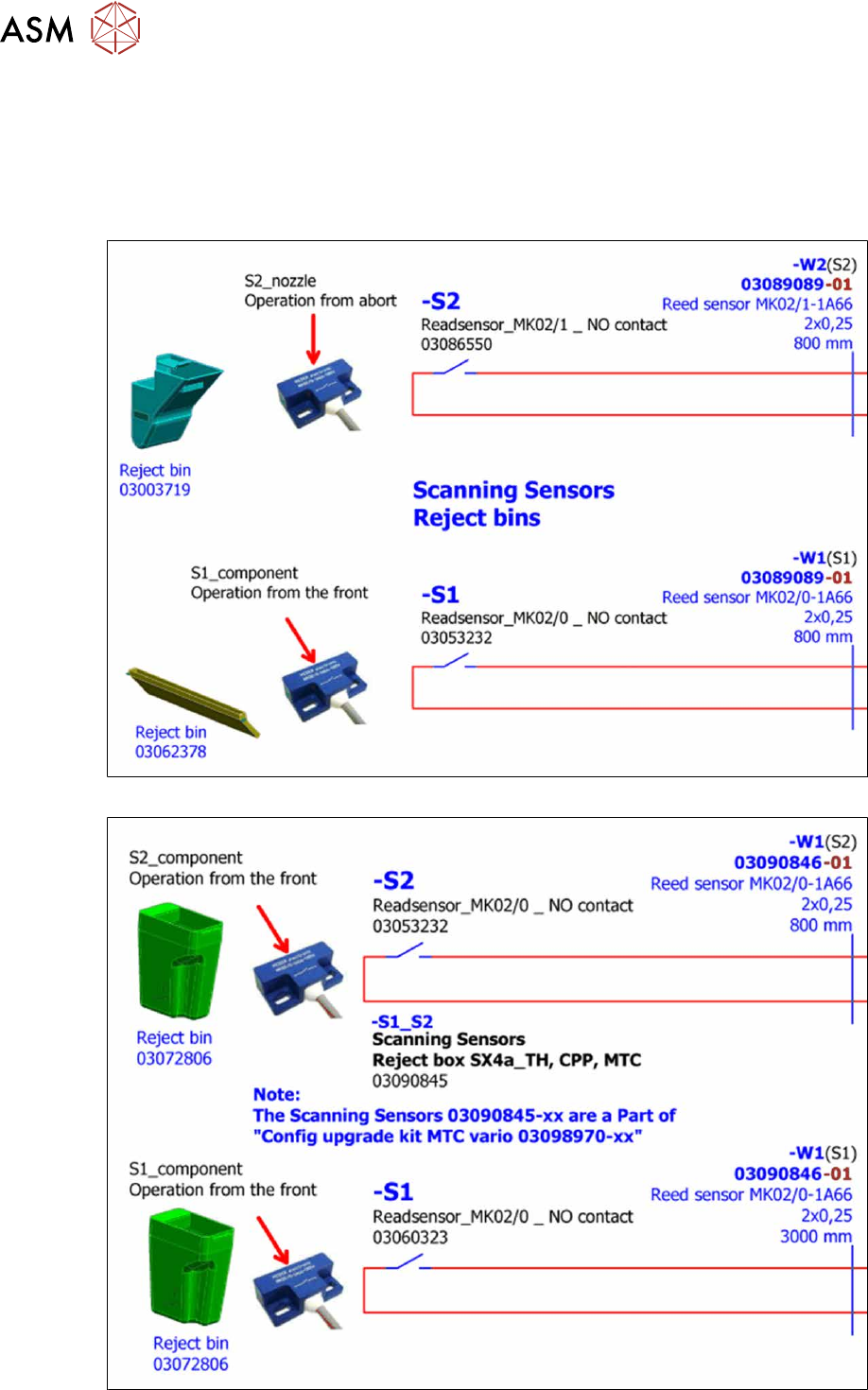
2.8.2 Reject bin and sensors - overview
For more information, refer to the circuit diagrams folder for your machine.
●
Detailed circuit diagrams folder for SIPLACE X-Series S (from Hxxxx) [DE+EN:00197920‑03]
●
Detailed circuit diagrams folder for SIPLACE X-Series S (from H1440) [DE EN: 00197920-04]
●
Detailed circuit diagrams folder for SIPLACE X-Series S (from H2500) [DE EN: 00198730-xx]
Fig.31: Sensors for reject bin SIPLACE X-Series S
Fig.32: Sensors for reject bin SIPLACE X-Series S
2 Basic Machine
2.8 Nozzle Changers and Reject Boxes
Service Manual SIPLACE X-Series S (from Hxxxx) 01/2021 39
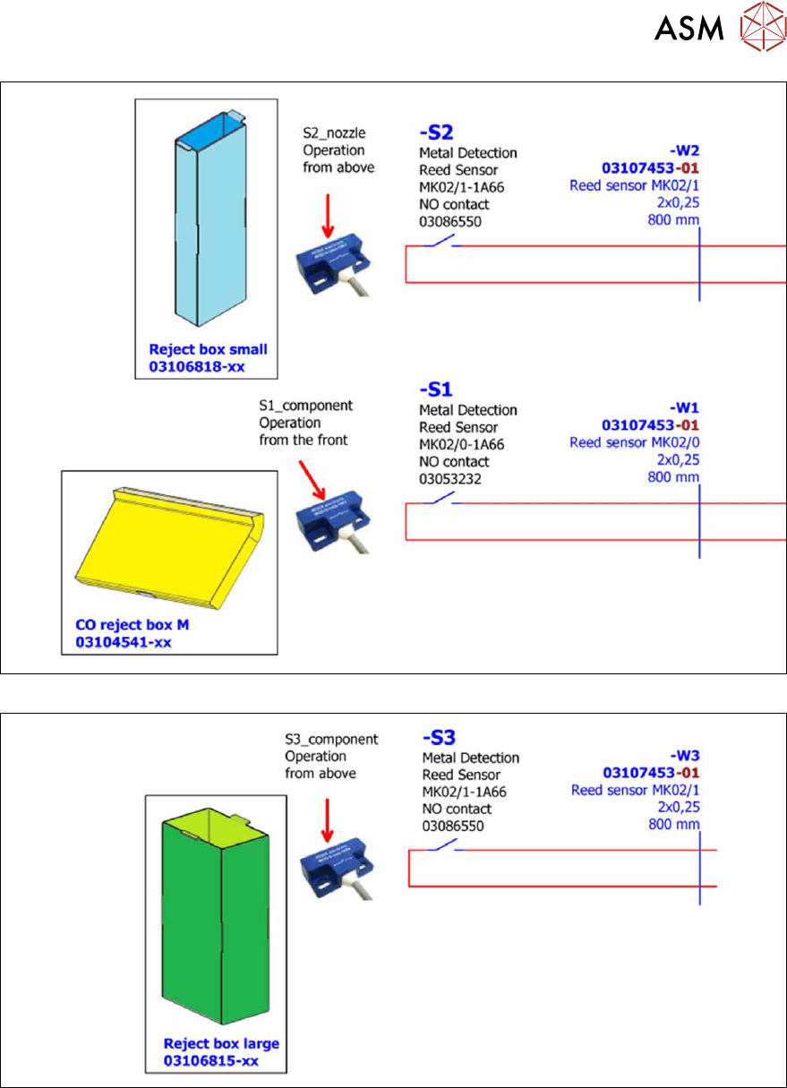
Fig.33: Sensors for reject bin SIPLACE X-Series S with JTF
Fig.34: Sensors for reject bin SIPLACE X-Series S with JTF
2 Basic Machine
2.8 Nozzle Changers and Reject Boxes
40 Service Manual SIPLACE X-Series S (from Hxxxx) 01/2021
2.8.3 Replacing the Nozzle Changer
NOTICE
Row two, MTC2, WPC
For more information about the row 2 nozzle changers and in combination with MTC2/
WPC, refer to the assembly instructions "NC row 2 - NC before MTC 2/
WPC" [DEEN:00197369‑xx].
Parts, equipment and tools
Select the relevant nozzle changers:
●
NC basic structure CPx/all assembly long [03147324–xx] (replaces [03103514‑xx]
[03070123‑xx])
●
NC CPx/all short [03147925‑xx] (replaces [03103649-xx] [03062463-xx])
●
Magazine holder assembly / NC P+P B series [03062453‑xx]
●
If required, NC shim plates [03021079-xx]
●
Depth measuring gauge (300mm) [03079617-xx]
●
Plastic plate
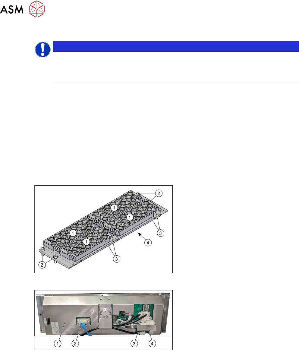
Overview
Fig.35: Nozzle changer with four nozzle magazines
1. Four nozzle magazines (4xxx/6xxx)
2. Four fixing screws
3. Four levers for removal of nozzle
magazines
4. Cover on the underside
The electronic and pneumatic compon-
ents are under the cover.
Fig.36: Overview of nozzle changers
1. Cover
2. Electrical connection
3. Compressed air connection
4. Valve