00198829-01_SM_X-Series-S_Hxxxx_EN.pdf - 第280页
8 Head exchange 8.10 Calibration 280 Service Manual SIPLACE X-Series S (from Hxxxx) 01/2021 ► Head and cameras – Pressure control valve (SIPLACE C&P20P) – Camera coefficient (unit nm/pixel), angle – Head offset (off…
8 Head exchange
8.10 Calibration
Service Manual SIPLACE X-Series S (from Hxxxx) 01/2021 279
8.10 Calibration
Overview
The following values are determined during calibration of the component camera:
●
Relation of camera pixel size to resolution of machine measurement system (X, Y).
●
The camera center point in the X and Y directions
●
Rotation angle of the CCD sensor in the camera
This is following by determining the head offset and the segment offsets for the top and bottom.
●
Head offset: the head offset is the distance between the PCB camera and the nozzle (seg-
ment1). The target is a fixed value (X=0 and Y=‑105mm) to which an offset value (from the
head calibration) is added.
●
Segment offset top: the top segment offset involves turning the calibration tool in the compo-
nent camera in 0°, 90°, 180° and 270°. The value determined is that of the rotating center of
the nozzle tip in relation to the component camera center in the X and Y direction.
●
Segment offset bottom: the bottom segment offset involves recording and measuring the
calibration tool in the 0°, 90°, 180° and 270° positions. The value determined is that of the ro-
tating center point of the nozzle tip when the Z Axis is extended in relation to the PCB camera.
Segment1 forms the reference (X=0,Y=0) to the other segments.
8.10.1 Calibration procedure
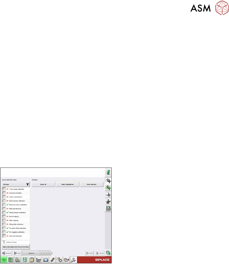
Fig.374: Calibration – all steps
All steps
●
Calibrating the travel range
●
Calibrating the axis zero point
●
System identification
●
Calibrating the PCB camera
●
Calibrating the PCB reference corner
●
Head and cameras
●
Calibrating the nozzle changer
●
Board mapping
●
Head mapping
●
Calibrating the lifting table
●
Pin picker, calibrating the offset
●
Calibrating the pin magazine
●
Calibrating the feed unit
Detailed procedure
► Calibrating the travel range
– Calibrating the min/max gantry travel distances
► Calibrating the axis zero point
► System identification
– Determining the moving load, friction and force constant for the selected axis to achieve a
better position for the axis.
► Calibrating the PCB camera
– Camera coefficient (illustration scale in nm/pixel)
– Calibrating the PCB camera center point
– Calibrating the PCB camera rotation to machine coordinate system
► Calibrating the PCB reference corner
8 Head exchange
8.10 Calibration
280 Service Manual SIPLACE X-Series S (from Hxxxx) 01/2021
► Head and cameras
– Pressure control valve (SIPLACE C&P20P)
– Camera coefficient (unit nm/pixel), angle
– Head offset (offset PCB camera to component camera)
– Segment offset II (bottom)
– Segment offset I (top)
► Calibrating the nozzle changer
– Calibrating the pickup position for all magazines
– Calibrating the pickup height
– Calibrating the reject position
► Board mapping
► Head mapping
► Calibrating the lifting table
► Pin picker, calibrating the offset
► Calibrating the pin magazine
► Calibrating the feed unit
8.10.2 Calibrating the heads and cameras (from SW7xx)
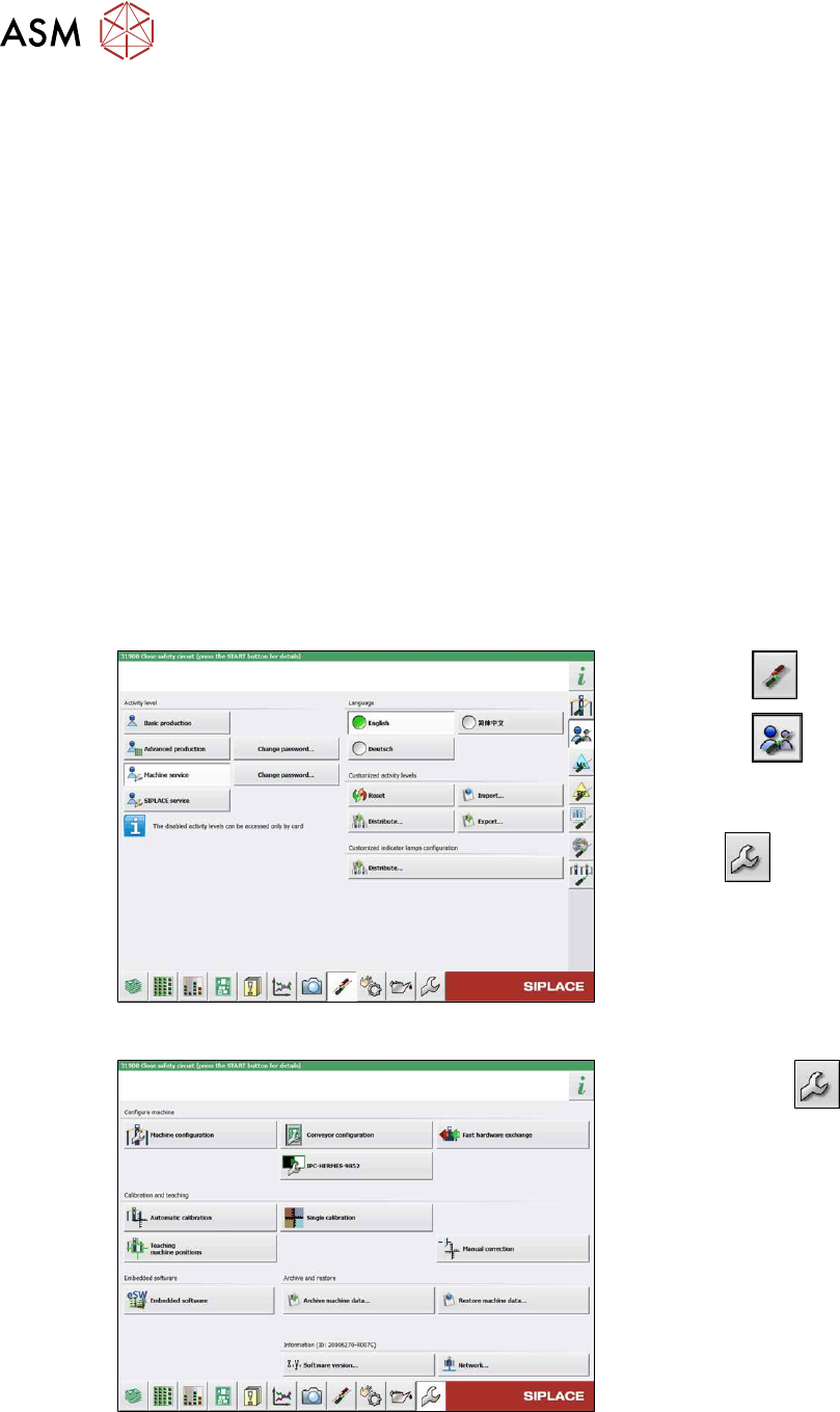
Fig.375: Select operator level
► Select the button.
► Select the button.
► Switch over to the operator level
Machine service
.
ð The button will be shown.
Fig.376: Service menu
► Use the button to switch to the
Service menu.
► Click the Automatic calibration but-
ton.
8 Head exchange
8.10 Calibration
Service Manual SIPLACE X-Series S (from Hxxxx) 01/2021 281
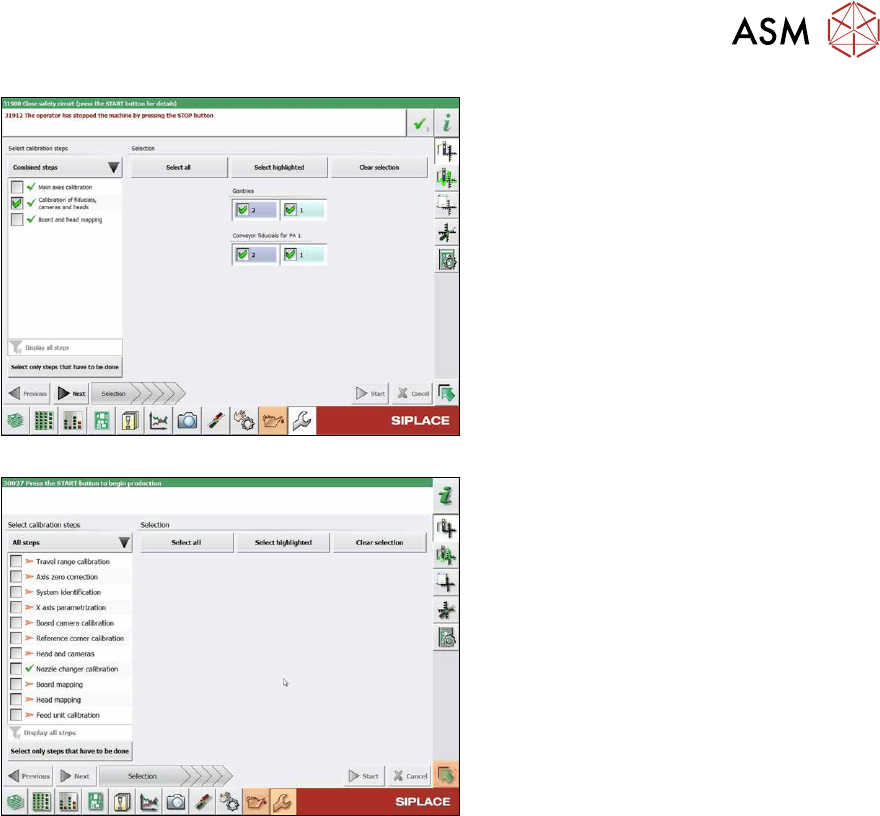
Fig.377: Calibration (combined steps)
Fig.378: Calibration (all steps)
You can choose between Combined steps
and All steps.
The procedure for All steps is described
below.
► Go to Select calibration steps and se-
lect All steps
.
► Choose Heads and cameras.
► On the next page, select the gantries
on which the heads to be calibrated are
located and then click on the Next
but-
ton.
Follow the instructions on the next pages:
► The next step is to check the calibration
conditions (nozzle, calibration tool etc.).
Follow the instructions provided.
After this step, the calibration will begin. All
required intermediate steps (head height
etc.) will be performed automatically.