00198829-01_SM_X-Series-S_Hxxxx_EN.pdf - 第362页
9 Component feeding 9.6 Smart Pin Support 362 Service Manual SIPLACE X-Series S (from Hxxxx) 01/2021 9.6.5 Replacing the control board Parts, equipment and tools ● Control board SPS [03089614Sxx] ● Assembly instructions …
9 Component feeding
9.6 Smart Pin Support
Service Manual SIPLACE X-Series S (from Hxxxx) 01/2021 361
9.6.4 Replacing the linear guide
Parts, equipment and tools
●
SPS linear guide [03084323Sxx]
●
Assembly instructions "Smart Pin Support" for SIPLACE X‑SeriesS [DEEN:00197394‑xx]
Overview
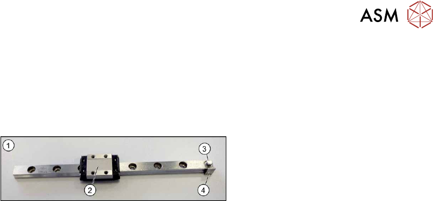
Fig.519: Linear guide
1. Linear guide
2. Trolley
3. Eyelet for hooking up the tension spring
4. Switch tag
Removal
► Switch off the machine, disconnect it from the power supply and secure it to prevent
unauthorized reactivation.
1.2 "Preparatory work..." [}16]
► Remove the Pin Picker.
9.6.1 "Replacing the Pin Picker Assembly" [}357]
► Remove the front section of the cylinder. For more information, read section 9.6.2 "Replacing
the front section of the cylinder" [}358].
► Remove the back section of the cylinder. For more information, read section 9.6.3 "Replacing
the back section of the cylinder" [}360].
► Remove the linear guide.
Installation
Follow the removal instructions in reverse order for installation. Also observe the following instruc-
tions:
► When you screw in the linear guide trolley, press it to the left, against the stop edge, so that it
lies flush against the base plate.
► Check the linear guide travel path. The linear guide must be easy to move along the whole
length.
► Check that the sensors switch properly.
The switch tag of the linear guide must have between 0.7 and 1.4 mm space to the sensor
above or below.
The top sensor must switch after 2mm when travelling downwards.
9 Component feeding
9.6 Smart Pin Support
362 Service Manual SIPLACE X-Series S (from Hxxxx) 01/2021
9.6.5 Replacing the control board
Parts, equipment and tools
●
Control board SPS [03089614Sxx]
●
Assembly instructions "Smart Pin Support" for SIPLACE X‑SeriesS [DEEN:00197394‑xx]
Overview
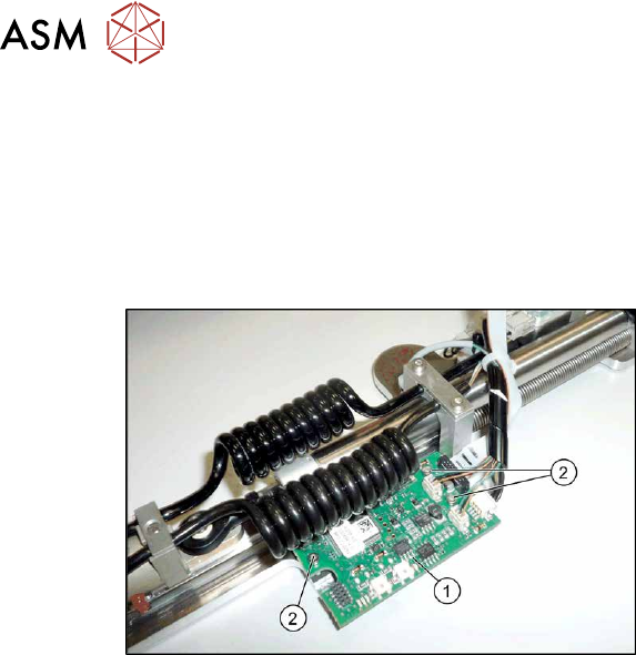
Fig.520: Control board
1. Control board
2. Three fastening screws for the control
board
Removal
► Switch off the machine, disconnect it from the power supply and secure it to prevent
unauthorized reactivation.
1.2 "Preparatory work..." [}16]
► Remove the Pin Picker.
9.6.1 "Replacing the Pin Picker Assembly" [}357]
► Unplug the electrical connections. Mark their positions, to make clear assignment easier later
on.
► Remove the three screws fastening the control board. Make sure that you do not lose the cor-
responding bushings on the back.
Installation
Follow the removal instructions in reverse order for installation. Also observe the following instruc-
tions:
► Perform a function check. Check whether the Pin Picker is recognized by the software and
also check the LEDs.
► See also 9.6.5.1 "Control board SPS" [}363]
9 Component feeding
9.6 Smart Pin Support
Service Manual SIPLACE X-Series S (from Hxxxx) 01/2021 363
9.6.5.1 Control board SPS
The control board SPS is fitted to the pin picker of the Smart Pin Support option.
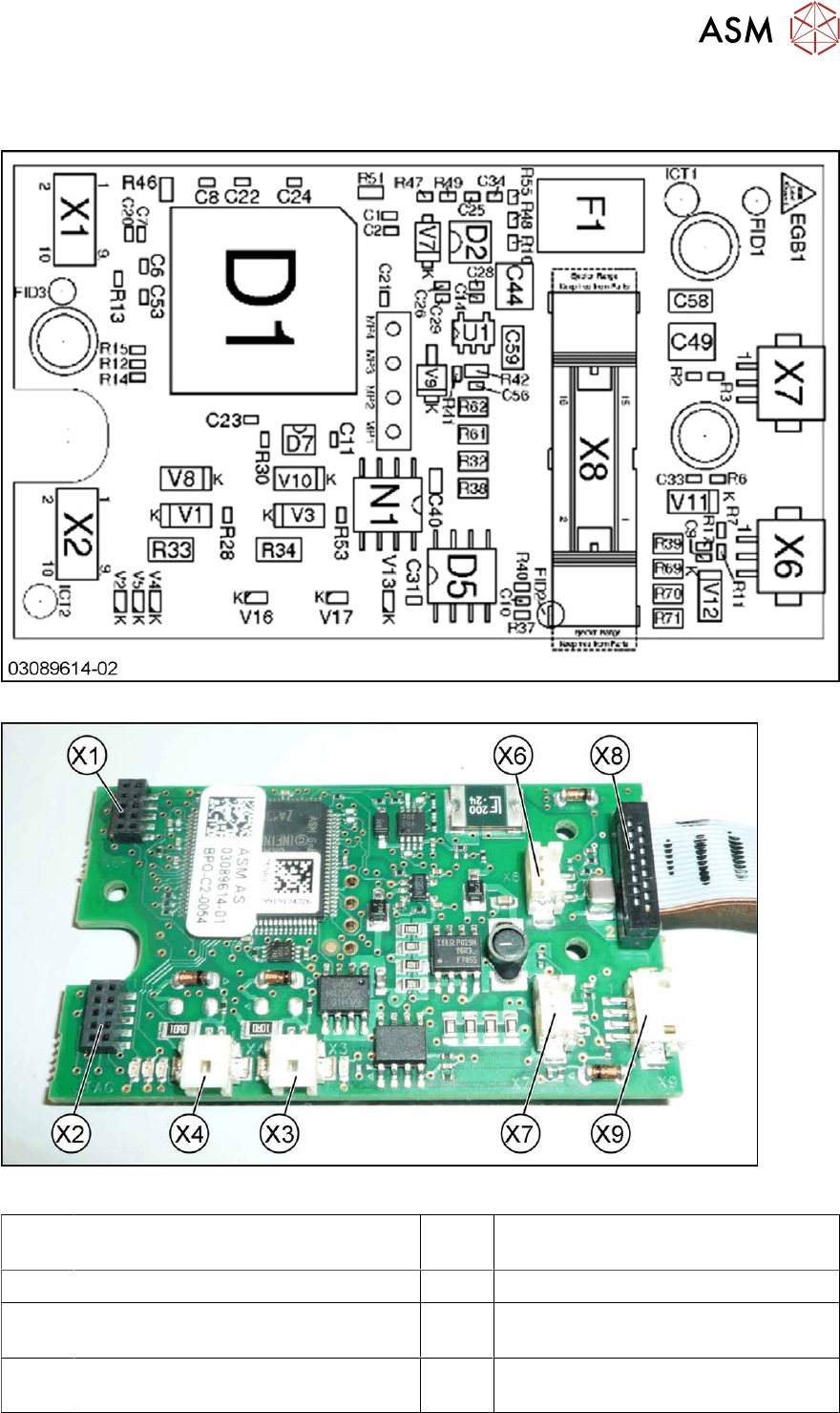
Fig.521: Control board – board overview
Fig.522: Control board – connections [03089614-01]
X1,X2 Diagnosis / Test connector X3,X4 Diagnosis / Test connector (not used
in FS02)
X5 Magnet (rear side) X6 Proximity switch down
X7 Proximity switch up X8 Connection to head interface
(FS01: ribbon cable on the rear side)
X9 Valves lifting cylinder and cleaning
pulse
On the back of the board:
Power electromagnet connection