00198829-01_SM_X-Series-S_Hxxxx_EN.pdf - 第155页
6 Gantries 6.7 Filter and pneumatics Service Manual SIPLACE X-Series S (from Hxxxx) 01/2021 155 Overview Fig.201: Pressure sensor on the gantry 1. Pressure sensor The pressure sensor is located on the vacuum distributor…
6 Gantries
6.7 Filter and pneumatics
154 Service Manual SIPLACE X-Series S (from Hxxxx) 01/2021
Removal
► Switch off the machine, disconnect it from the power supply and secure it to prevent
unauthorized reactivation.
1.2 "Preparatory work..." [}16]
► Switch off the compressed air supply
5.2 "Disabling the compressed air supply" [}86]
► Dismantle the Vision Head Interface.
6.4.8 "Replacing the Vision head interface (VHI)" [}136]
► Dismantle the head interface.
6.4.6 "Replacing the Head Interface" [}131]
► Mark all pneumatic connections to the vacuum distributor, to make clear assignment easier
later on.
► Unplug all pneumatic connections to the vacuum distributor.
► Remove the screws fastening the vacuum distributor and then remove the vacuum distributor.
Installation
Follow the removal instructions in reverse order for installation.
6.7.2 Replacing the pressure sensor
NOTICE
The pressure sensor is only needed if there vacuum pump is fitted and for SIPLACE
C&P20x.
In this case, the pressure sensor is essential for operation of the placement machine.
Parts, equipment and tools
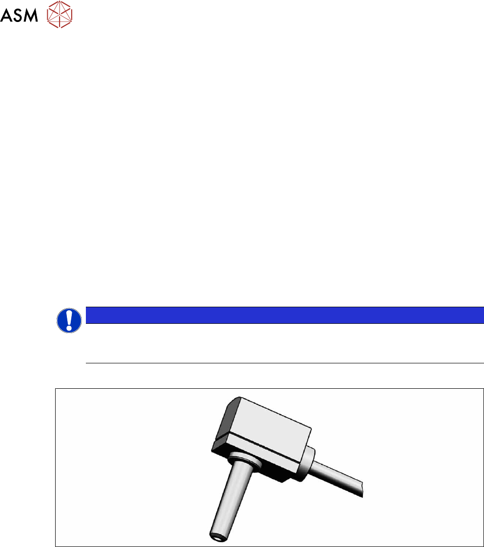
Fig.200: Pressure sensor
●
Upgrade kit - pressure sensor for vacuum SIPLACE C&P20P [03108457‑xx]
6 Gantries
6.7 Filter and pneumatics
Service Manual SIPLACE X-Series S (from Hxxxx) 01/2021 155
Overview
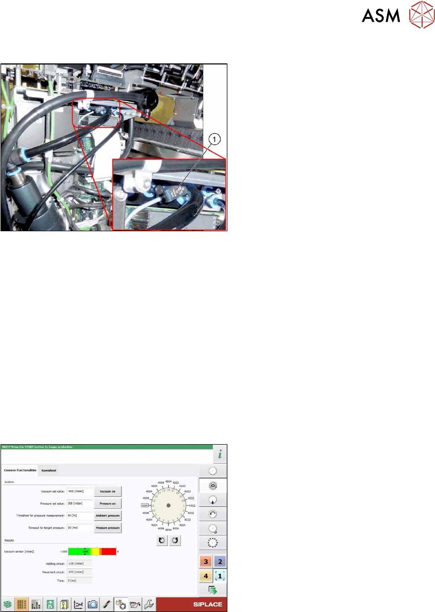
Fig.201: Pressure sensor on the gantry
1. Pressure sensor
The pressure sensor is located on the
vacuum distributor of the gantry and is con-
nected to the head interface (X8) adaptor.
Removal
► Switch off the machine, disconnect it from the power supply and secure it to prevent
unauthorized reactivation.
1.2 "Preparatory work..." [}16]
► Switch off the compressed air supply
5.2 "Disabling the compressed air supply" [}86]
► If there is a cover above the boards, dismantle it.
6.4.1 "Replacing the cover on the boards" [}118]
► Unplug the electrical connection of the pressure sensor to the head interface (X8).
► Disconnect the pressure sensor from the vacuum distributor on the gantry.
Installation
Follow the removal instructions in reverse order for installation. Observe the following note:
Fig.202: Checking the pressure sensor
► Check the pressure sensor at the sta-
tion software.
6 Gantries
6.8 Sensor, motor and guide trolley
156 Service Manual SIPLACE X-Series S (from Hxxxx) 01/2021
6.8 Sensor, motor and guide trolley
6.8.1 Replacing the head plate sensors (temperature sensor)
Parts, equipment and tools
●
Gantry sensor module HCU [03071974-xx]
●
Gap fillers, where required / GTQ2100 d:4.6mm 7x16mm [03014285‑xx]
Overview
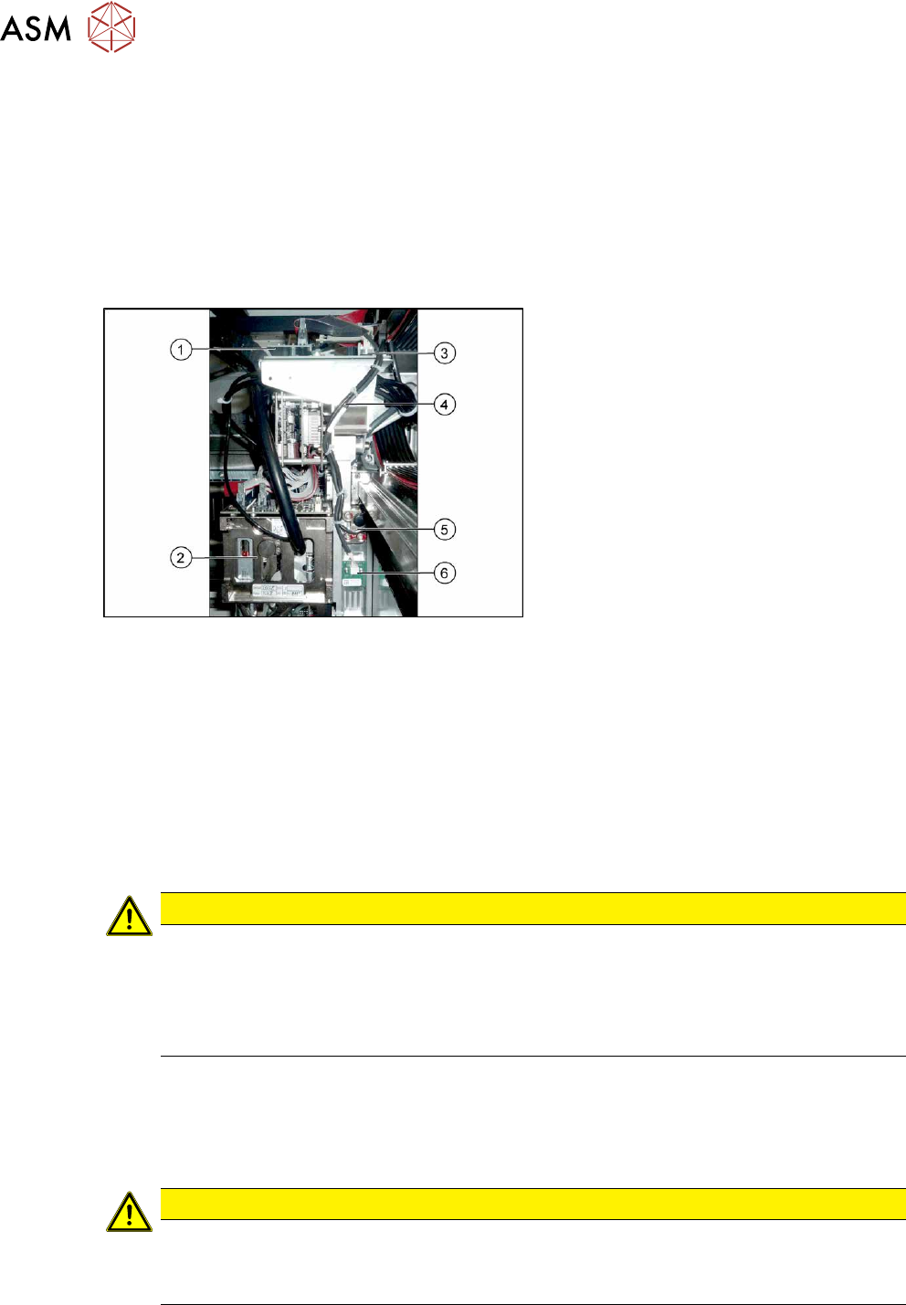
Fig.203: Overview of temperature sensor
1. Vision Head Interface
2. Placement head on gantry
3. Head interface
4. Cable from temperature sensor and in-
cremental encoder X axis to head inter-
face
5. The X axis incremental encoder
6. Temperature sensor
Removal
► Switch off the machine, disconnect it from the power supply and secure it to prevent
unauthorized reactivation.
1.2 "Preparatory work..." [}16]
► You can also dismantle the pin picker, if present, for better access.
9.6.1 "Replacing the Pin Picker Assembly" [}357]
► Unplug the cable from the head interface, unthread it and remove all cable ties.
► Remove the two screws fastening the board and then pull it off.
CAUTION
Rubber foam
Under this board there is heat-conductive rubber foam (gap filler) or heat-conductive paste.
► Do not remove the heat-conductive rubber foam.
► The heat-conductive paste needs to be replaced during refitting. You may need to
remove the old heat-conductive paste, if it is still present.
Installation
► Fix the board into place with the two fastening screws.
► Insert the cable, thread through to the head interface and then connect. Replace any opened
cable ties.
CAUTION
Check how the cables are run!
► Make sure that the end stops (red buffers) do not rub against the cable of the board.
► Make sure that the cable for the board can not collide with the X axis end stopper.