00198829-01_SM_X-Series-S_Hxxxx_EN.pdf - 第24页
2 Basic Machine 2.2 Replacing the gas pressure shock absorber on the cover 24 Service Manual SIPLACE X-Series S (from Hxxxx) 01/2021 2.2 Replacing the gas pressure shock absorber on the cover Parts, equipment and tools F…
2 Basic Machine
2.1 Overview of X-Series S Machines
Service Manual SIPLACE X-Series S (from Hxxxx) 01/2021 23
2 Basic Machine
DANGER
Observe User Manual
► Please observe the safety instructions in the user manual for all work!
2.1 Overview of X-Series S Machines
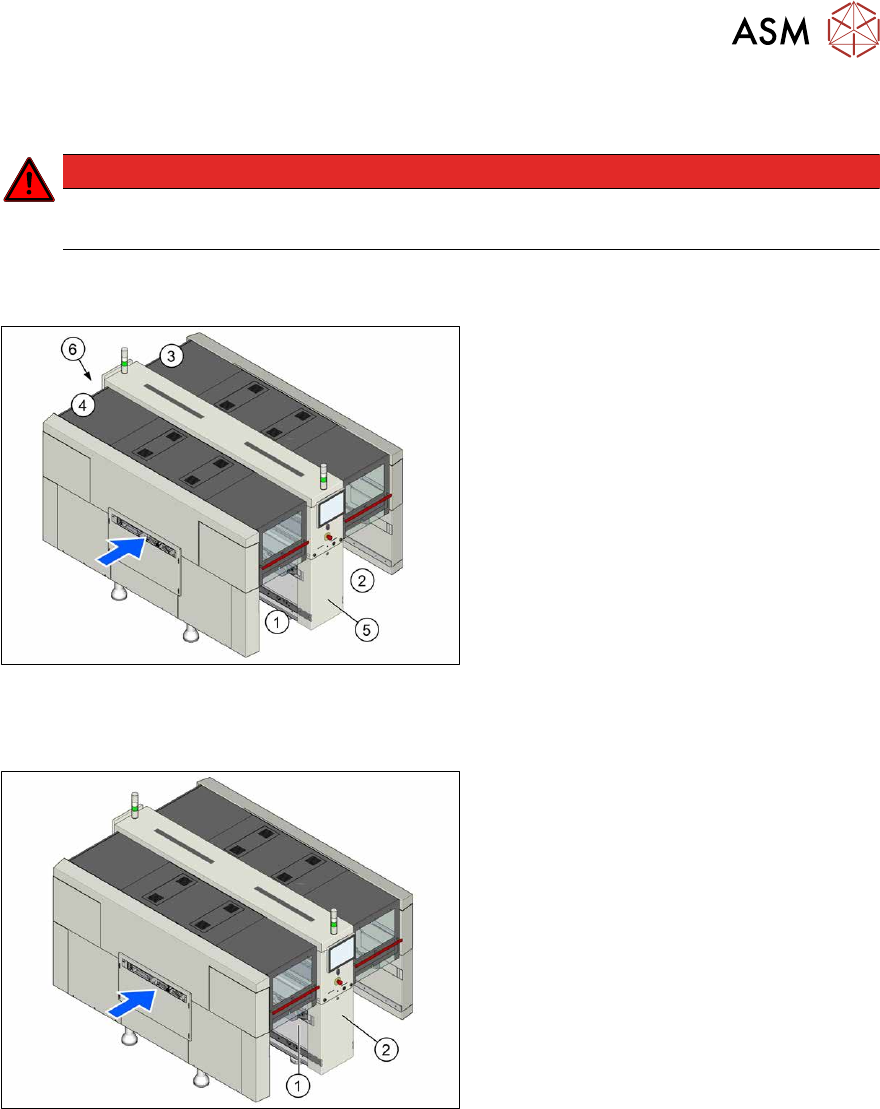
Fig.5: Machine overview
1. Location 1
2. Location 2
3. Location 3
4. Location 4
5. MGCU, BoxPC, I/O modules
6. Power supply
2.1.1 Serial Number of Module
Fig.6: Typeplate
The serial number of your placement
machine can be found at location1, on the
typeplate(1)
and behind the distributor
door(2)
, on the right, above the distributor.
2 Basic Machine
2.2 Replacing the gas pressure shock absorber on the cover
24 Service Manual SIPLACE X-Series S (from Hxxxx) 01/2021
2.2 Replacing the gas pressure shock absorber on the cover
Parts, equipment and tools
Fig.7: Gas pressure shock absorber D3D3B90-135-430-004/230N [03086743-xx]
●
Gas pressure shock absorber D3D3B90-135-430-004/230N [03086743-xx] (replaces:
[03057763‑xx]) (2x per cover)
●
Loctite 638 [00317731-xx], if required (for loose screwed fixtures)
Removal
► Switch off the machine, disconnect it from the power supply and secure it to prevent
unauthorized reactivation.
1.2 "Preparatory work..." [}16]
► Open the cover and fix it in a position which gives you best access for working and which en-
sures that it cannot close itself on its own.
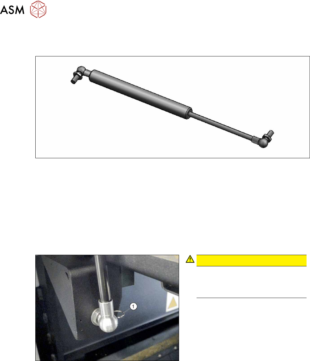
Fig.8: Circlip
CAUTION!
Fasten the cover!
As soon as one circlip is released, the
cover can fall down if not sufficiently
fixed.
.
► Release and remove the circlip (1) on
the bottom holder of the gas pressure
shock absorber.
► Repeat this on the top holder of the gas
pressure shock absorber.
► Remove the gas pressure shock absorber from the spherical head on the top and bottom
holder.
2 Basic Machine
2.3 Guide Rollers on the Covers
Service Manual SIPLACE X-Series S (from Hxxxx) 01/2021 25
Installation
Follow the removal instructions in reverse order for installation. Also observe the following instruc-
tions:
Fig.9: Gas pressure shock absorber
► Observe the correct installation direc-
tion for the gas pressure shock ab-
sorber(1)
.
► You may have to compress the gas
pressure shock absorber slightly when
installing it.
► Fix the gas pressure shock absorber
into place with the circlips.
► Check the cover for ease of movement and adjust if required.
2.4 "Setting the Covers" [}27]
2.3 Guide Rollers on the Covers
NOTICE
Example shown as diagram
The following sections are described using the example of a SIPLACE SX1 machine. The
procedure is the same for other machine types. Any relevant differences will be mentioned
explicitly.
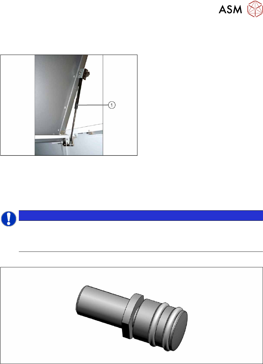
Parts
Fig.10: Guide roller [03078561-xx]
●
Per cover:
– 2x roller assy – 1 unit [03078561-xx]
– 2x DIN EN ISO 4028 M8x16-A2-21H – pack of 10 [03027433‑xx] (replaces[00304354‑xx])
or
2x DIN EN ISO4026-M8x16-A2-21H - pack of 10 [03025582-xx]
Equipment and tools
●
Fork wrench, size 10
●
Allen key