00198829-01_SM_X-Series-S_Hxxxx_EN.pdf - 第162页
7 Conveyor 7.2 Loosening the Conveyor Side Clamps 162 Service Manual SIPLACE X-Series S (from Hxxxx) 01/2021 Function description The width is adjusted by means of a motor as programmed. When using dual conveyor systems …
7 Conveyor
7.1 Conveyor X Series S
Service Manual SIPLACE X-Series S (from Hxxxx) 01/2021 161
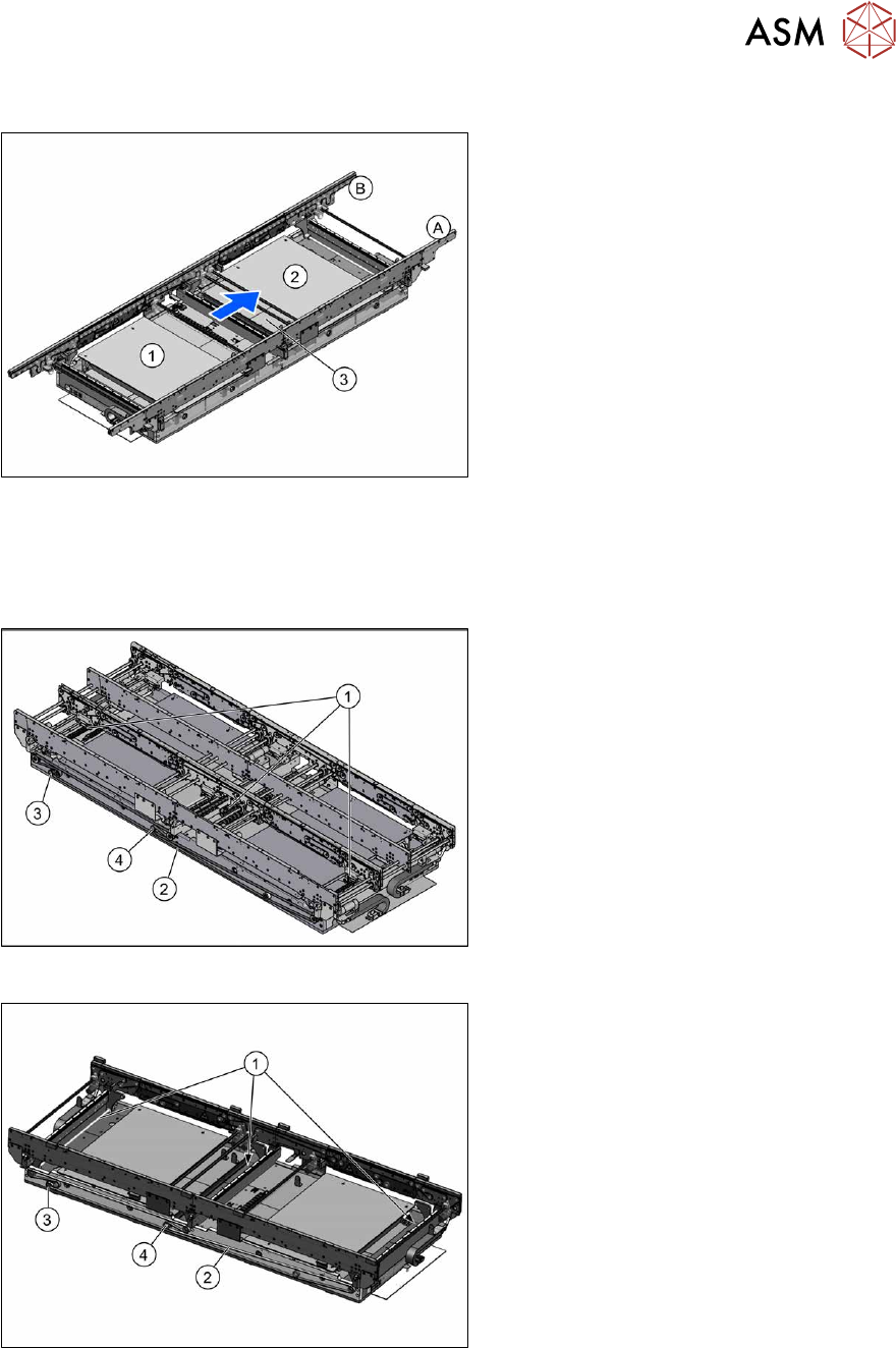
7.1.4 Single conveyor, heavy board 8kg
Fig.208: Overview of single conveyor, heavy board 8kg
1. Placement area 1
2. Placement area 2
3. Conveyor control TSP420 (2x, under
the covers)
7.1.5 Width Adjustment
Overview
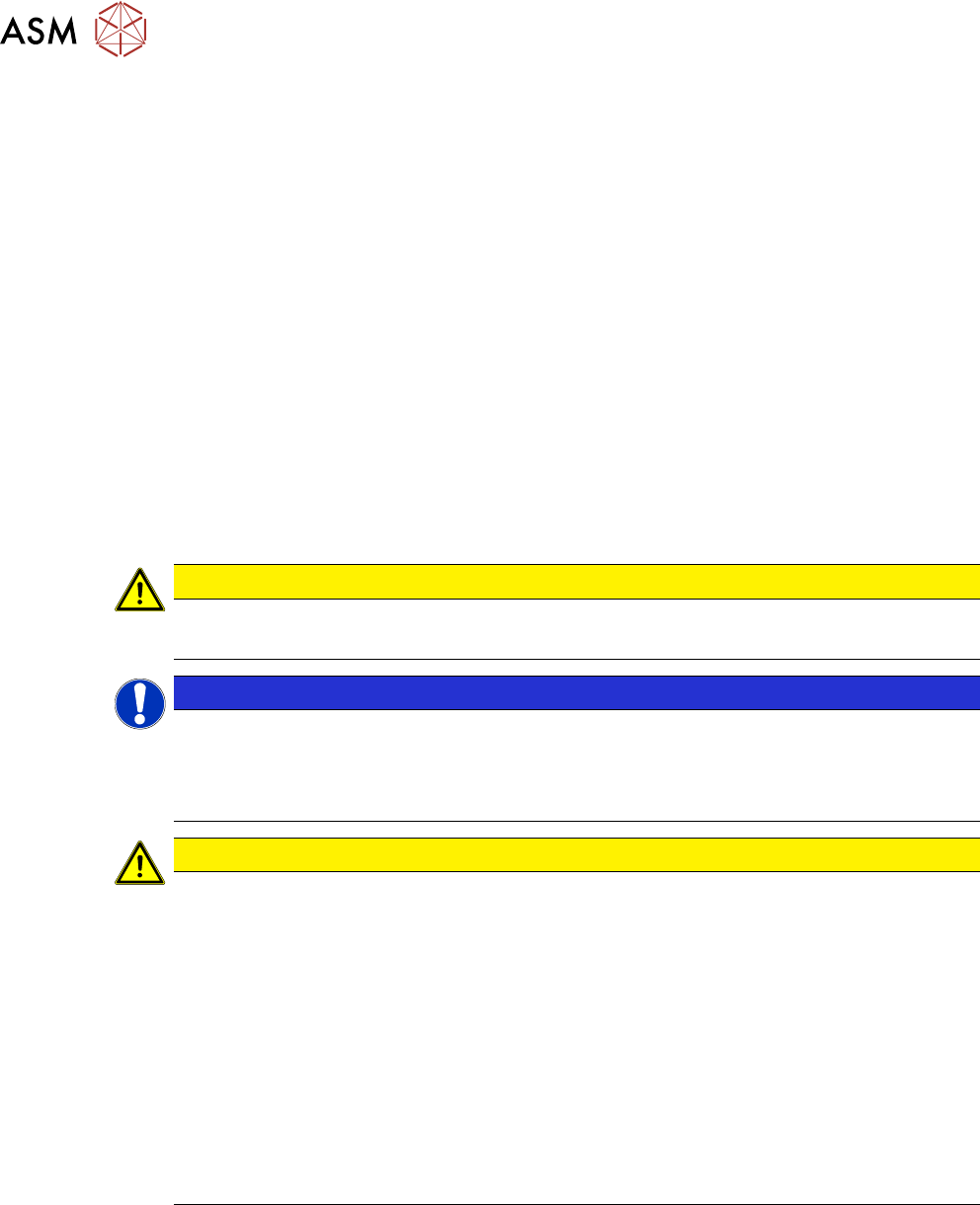
Fig.209: Width adjustment for dual conveyor (DC)
Dual conveyor
1. Adjustment units (3x)
2. Toothed belt of width adjustment
3. Drive unit of width adjustment
4. Movable idler pulley
Fig.210: Width adjustment for single conveyor (SC)
Single conveyor
1. Recirculating ball screws (3x)
2. Toothed belt of width adjustment
3. Drive unit of width adjustment
4. Movable idler pulley
7 Conveyor
7.2 Loosening the Conveyor Side Clamps
162 Service Manual SIPLACE X-Series S (from Hxxxx) 01/2021
Function description
The width is adjusted by means of a motor as programmed.
When using dual conveyor systems, differing widths can be set for the two conveyor lanes. The
width adjustment uses a motor with its own measuring system, meaning that the PCB width can be
set independently of other machine components (e.g. the Y gantry).
The PCB width is adjusted using the width adjustment units. These are moved synchronously back
and forth by the drive motor, with the help of recirculating ball screws and a toothed belt.
The side clamp is released by moving out fixing pins. At the same time, the side is fixed to the ad-
justment units. After reaching the new PCB width, the fixing pins move back in. The side panel is
then clamped again.
In the single conveyor, the recirculating ball spindles are directly connected with the moveable
conveyor side. Conversion from a fixed side right to a fixed side left is not possible.
7.2 Loosening the Conveyor Side Clamps
Many tasks performed on the conveyor require that the conveyor sides are moved when the
machine is switched off. In addition, when using a dual conveyor, the conveyor side clamps can be
released as follows.
CAUTION
Lifting table
► The lifting table must always be lowered when the conveyor sides are moved.
NOTICE
Single conveyor
There are no clamps on a single conveyor.
► You can move the flexible side here by carefully pulling on the width adjustment
toothed belt.
CAUTION
Moving the conveyor sides
The conveyor sides are highly sensitive and should therefore if possible be moved without
releasing the brakes.
Irreparable damage could otherwise be caused to the conveyor sides.
For this reason, try the following options in the order listed:
► We recommend that you use the software to help you move the conveyor sides.
► If this is not possible, the conveyor sides of the dual conveyors can also be moved by
manually docking in the adjustment units (direct switching of valves for the width ad-
justment). Make sure that the cylinders engage in all clamping units of a particular
conveyor side. The conveyor sides can then be moved by carefully pulling the toothed
belt of the width adjustment unit.
► If this is not possible either, the brakes of the dual conveyors can manually be re-
leased using a pin. Take special care not to distort the conveyor sides.
7 Conveyor
7.2 Loosening the Conveyor Side Clamps
Service Manual SIPLACE X-Series S (from Hxxxx) 01/2021 163
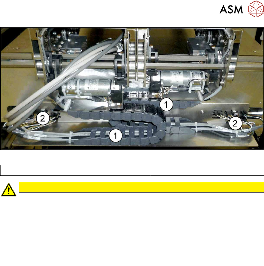
Fig.211: Trailing cable and interface connector
1 Trailing cable 2 Interface connector
CAUTION
Outer conveyor sides can only be moved to center
If the outer conveyor sides are manually moved, the trailing cable could collide with the interface
connectors underneath the conveyor sides. To avoid this, observe the following points:
► The conveyor sides A, B and C may only be moved as far as the "stopper right side D"
on the outermost left edge of the lifting table plate of conveyor lane 1.
► The conveyor sides D, C and B may only be moved as far as the "stopper left side A"
on the outermost right edge of the lifting table plate of conveyor lane 2.
ð If the conveyor sides are moved using the software, this will automatically be taken
into account.
7.2.1 Manually Moving the Conveyor Sides with the Help of the Adjustment Units
Docking in the adjustment units
If you are unable to move the sides with the software (e.g. due to a sensor error), proceed as follows:
► Switch off the machine, disconnect it from the power supply and secure it to prevent
unauthorized reactivation.
1.2 "Preparatory work..." [}16]
► Switch off the BoxPC.
► Dismantle the lifting table plate at location 3.
► Switch the machine on (without BoxPC). The machine is now supplied with compressed air.