00198829-01_SM_X-Series-S_Hxxxx_EN.pdf - 第368页
9 Component feeding 9.6 Smart Pin Support 368 Service Manual SIPLACE X-Series S (from Hxxxx) 01/2021 Overview Fig.529: Coiled cable – old and new version A = Old version of Pin Picker B = New version of Pin Picker 1. St…
9 Component feeding
9.6 Smart Pin Support
Service Manual SIPLACE X-Series S (from Hxxxx) 01/2021 367
Removal
► Switch off the machine, disconnect it from the power supply and secure it to prevent
unauthorized reactivation.
1.2 "Preparatory work..." [}16]
► Remove the Pin Picker.
9.6.1 "Replacing the Pin Picker Assembly" [}357]
► Remove the strain relief on the back section of the cylinder.
► Remove the strain relief on the pneumatic cylinder guidance.
► Remove the coil hose on the pneumatic connection of the return cylinder.
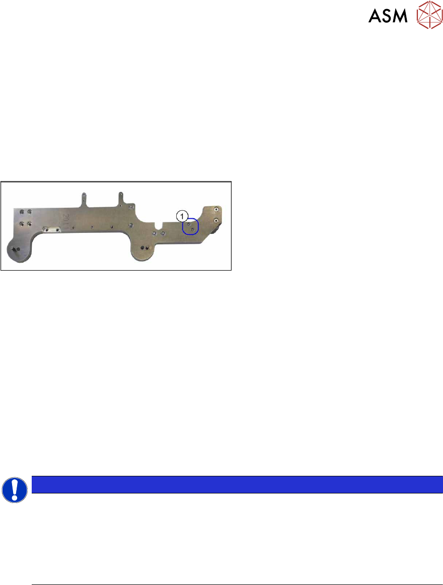
Fig.528: Screws fastening the valve terminal
► Remove the two screws fastening the
(1)
valve terminal. These are on the
back of the Pin Picker.
► Remove the coil hose from the valve terminal.
Installation
Follow the removal instructions in reverse order for installation. Observe the following note:
► Make sure that the coil hose does not rub against anything. It is important that the coil hose
and the coiled cable do not touch when fully extended.
9.6.9 Replacing the coiled cable
Parts, equipment and tools
●
Coiled cable [03090273-xx]
●
Safety varnish red [00318197-xx]
●
Assembly instructions "Smart Pin Support" for SIPLACE X‑SeriesS [DEEN:00197394‑xx]
NOTICE
Replacing the strain reliefs
When working with the coil hose or the coiled cable, observe the technical information
"Smart Pin Support: Replacing Faulty Coiled Cables at the Pin Picker (Update)" [DE:
TI2013-09D04] [EN: TI2013-09E04].
► If needed, order the following additional parts:
Cover plate/SPS [03102482-xx]
Hose holder/SPS [03102480-xx]
9 Component feeding
9.6 Smart Pin Support
368 Service Manual SIPLACE X-Series S (from Hxxxx) 01/2021
Overview
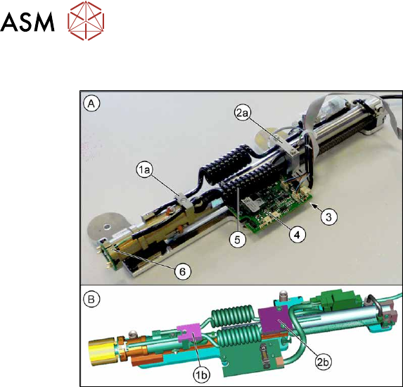
Fig.529: Coiled cable – old and new version
A = Old version of Pin Picker
B = New version of Pin Picker
1. Strain relief on back section of cylinder
1a: Old version
1b: New version
2. Strain relief on the pneumatic cylinder
guidance
2a: Old version
2b: New version
3. Coiled cable connection (on the under-
side of the control board)
4. Control board
5. Coiled cable
6. Connection of the coiled cable to the
front section of the cylinder
Removal
► Switch off the machine, disconnect it from the power supply and secure it to prevent
unauthorized reactivation.
1.2 "Preparatory work..." [}16]
► Remove the Pin Picker.
9.6.1 "Replacing the Pin Picker Assembly" [}357]
► Remove the strain relief on the back section of the cylinder.
► Remove the strain relief on the pneumatic cylinder guidance.
► Unplug the coiled cable from the front section of the cylinder.
► Unthread the coiled cable as far as the control board.
► Unplug the coiled cable from the control board.
► Remove the coiled cable.
Installation
Follow the removal instructions in reverse order for installation. Also observe the following instruc-
tions:
► Make sure that the cables are run correctly.
► Make sure that the coiled cable does not rub against anything. It is important that the coil hose
and the coiled cable do not touch when fully extended.
► Secure the lower connector on the front part of the cylinder with safety varnish.
► Replace any opened cable ties.
9 Component feeding
9.6 Smart Pin Support
Service Manual SIPLACE X-Series S (from Hxxxx) 01/2021 369
9.6.10 Replacing the Round Cable
Parts, equipment and tools
●
Connection cable SPS [03091099-xx]
NOTICE
Control board SPS
The new SPS connection cable and the old SPS control board are not compatible with one
another.
► Replace the SPS control board if required.
Overview
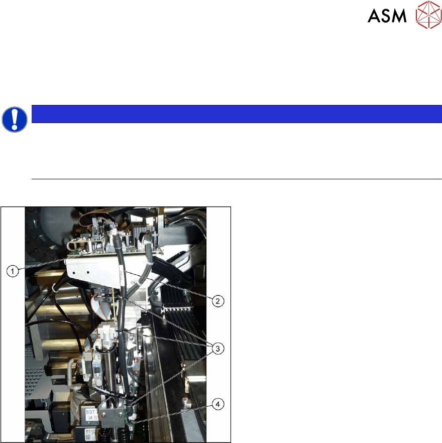
Fig.530: Round cable
1. Head interface on the gantry
2. Round cable
3. Cable tie
4. SPS control board on the Pin Picker
Removal
► Switch off the machine, disconnect it from the power supply and secure it to prevent
unauthorized reactivation.
1.2 "Preparatory work..." [}16]
► Disconnect the round cable from the head interface.
► Disconnect the round cable from the SPS control board.
► Remove the round cable. To do this, open the cable ties on the round cable.
Installation
Follow the removal instructions in reverse order for installation. Also observe the following instruc-
tions:
► Replace the cable ties.
► Make sure that the cable does not get in-between the X axis buffers.