00198829-01_SM_X-Series-S_Hxxxx_EN.pdf - 第307页
9 Component feeding 9.1 Cutter Service Manual SIPLACE X-Series S (from Hxxxx) 01/2021 307 Installation ► Fit the new cable set and adjust the sensors to the correct position. Follow the removal instructions in reverse or…
9 Component feeding
9.1 Cutter
306 Service Manual SIPLACE X-Series S (from Hxxxx) 01/2021
9.1.13 Replacing the cutter cable
Parts
03063590-xx Cutter cable X-Series
Equipment and tools
00353832-xx Allen key set
Wire cutters
Cable tie
Overview
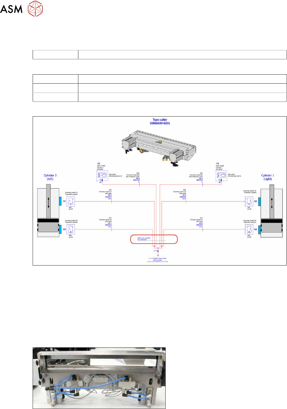
Fig.425: Electrical connections
Removal
► Switch off the machine, disconnect it from the power supply and secure it to prevent
unauthorized reactivation.
1.2 "Preparatory work..." [}16]
► Switch off the compressed air supply
5.2 "Disabling the compressed air supply" [}86]
► Vent the cutter. It must be totally depressurized.
9.1.2 "Venting compressed air at the cutter" [}284]
Fig.426: Cutter cable
► Disconnect all sensors and plugs and
remove the cable set completely.
Mark the position of old sensors, espe-
cially the sensors responsible for posi-
tioning the short-stroke cylinders.
9 Component feeding
9.1 Cutter
Service Manual SIPLACE X-Series S (from Hxxxx) 01/2021 307
Installation
► Fit the new cable set and adjust the sensors to the correct position.
Follow the removal instructions in reverse order for further installation.
► Attach cables ties if necessary (strain relief).
9.1.14 Replacing the throttle valve
Parts
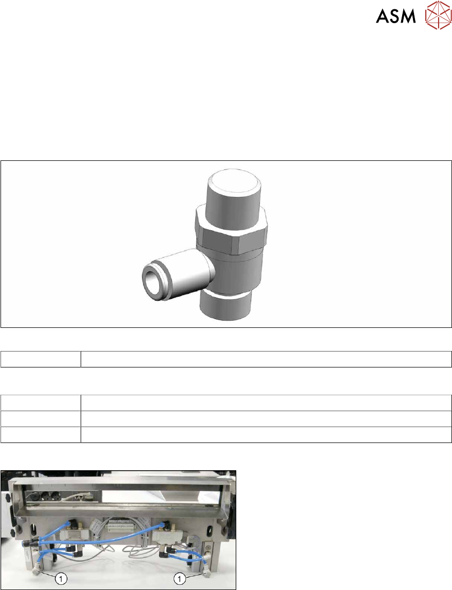
Fig.427: Throttle valve
03000600‑xx Throttle valve AS2201F-02-06SA
Equipment and tools
00096290-xx Fork wrench set
Wire cutters
Cable tie
Overview
Fig.428: Throttle valves on cutter
1. Throttle valves
The throttle valves are installed at the lower
sides of the short-stroke cylinders.
9 Component feeding
9.1 Cutter
308 Service Manual SIPLACE X-Series S (from Hxxxx) 01/2021
Removal
► Switch off the machine, disconnect it from the power supply and secure it to prevent
unauthorized reactivation.
1.2 "Preparatory work..." [}16]
► Switch off the compressed air supply
5.2 "Disabling the compressed air supply" [}86]
► Vent the cutter. It must be totally depressurized.
9.1.2 "Venting compressed air at the cutter" [}284]
► Try to perform the exchange on the installed cutter.
If access is too limited, remove the cutter from the machine.
Replacing the Cutter on the COT Insert [03066690-xx]
Fig.429: Removing the throttle valve
► Disconnect the air tube(1) from the
throttle valve(2)
.
► Turn the throttle valve in the direction
"-" and count the turns. Note the num-
ber.
► Remove the throttle valve by using a
SW17 spanner(3)
.
Installation
► Fit the new throttle valve. Take care of the silicon sealing.
► Close the throttle valve completely in direction "-" and open it again in direction “+” by counting
the noted turnings.
This will ensure a working pre-adjustment for starting the final setting later on.
► Connect the air tube.
Follow the removal instructions in reverse order for further installation.
► Set the new throttle valve (see below).
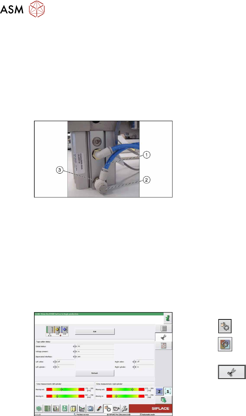
9.1.14.1 Times for setting the restrictor on the cutter
The menu is available from SW707.1.
Fig.430: Measuring times
► Switch over to Check sensors and
functions .
► Select the button.
► Select Location.
► Select the button.
► Select Cut to start test.
You have to select the Cut
button at
least two times (one for each side).
► Check the measured times.
► Repeat if necessary.