00198829-01_SM_X-Series-S_Hxxxx_EN.pdf - 第269页
8 Head exchange 8.6 Replacing the SIPLACE C&P20P2 Service Manual SIPLACE X-Series S (from Hxxxx) 01/2021 269 Fig.359: Fastening screws ► Tighten the four screws fastening the head (1) (M4, torque 2.7Nm). CAUTIO…
8 Head exchange
8.6 Replacing the SIPLACE C&P20P2
268 Service Manual SIPLACE X-Series S (from Hxxxx) 01/2021
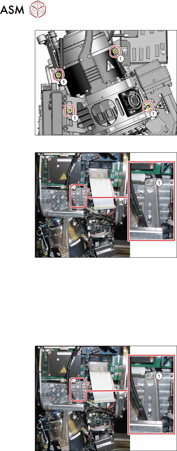
Fig.356: Fastening screws
► Unscrew all four screws(1) (M4)
fastening the heads with a long Allen
key.
These four screws are captive screws
which remain on the head.
Fig.357: Fastening screws
► Carefully lift the placement head out of
the locating pins on the head plate and
off the hook(1)
.
► Placing the head into the head transport box
Installation
► For compressed air mode, the placement head must be converted using the "Hold circuit
assembly/C&P20" [03005123Sxx].
► If you replace the placement head without the component camera, then you will need to fit the
old camera into the new head. Read the service manual for your placement head for more in-
formation.
In this case a full calibration is necessary after fitting.
Fig.358: Fastening screws
► Carefully hang the placement head on
the hook(1)
.
► Lift the placement head slightly, so that
you can thread it into the locating pins
on the head plate.
8 Head exchange
8.6 Replacing the SIPLACE C&P20P2
Service Manual SIPLACE X-Series S (from Hxxxx) 01/2021 269
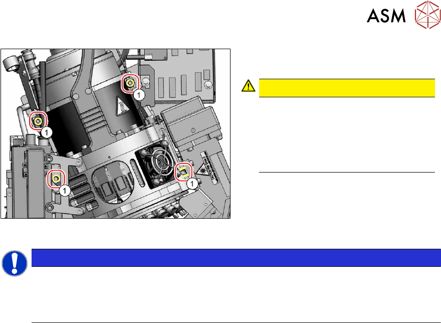
Fig.359: Fastening screws
► Tighten the four screws fastening the
head(1)
(M4, torque 2.7Nm).
CAUTION!
Do not distort
The screw must be turned 3-4 times
before the torque is reached.
If the torque is reached after only one
rotation, this probably means that the
screw has been inserted at a tilt.
.
NOTICE
Various hose lengths on SIPLACE X-Series S
The hose to the pressure control valve will vary in length, depending on the installation loc-
ation (standard gantry or rotated gantry).
► Shorten or replace the hose, where necessary.
Follow the removal instructions in reverse order for further installation.
See also
2 8.9 "Installation Positions on the Head Plate" [}278]
8 Head exchange
8.7 Replacing the SIPLACE CPP/M
270 Service Manual SIPLACE X-Series S (from Hxxxx) 01/2021
8.7 Replacing the SIPLACE CPP/M
Parts, equipment and tools
Fig.360: SIPLACE CPP with camera
●
SIPLACE CPP with camera SST29 [03070108-xx] or
SIPLACE CPP without camera [03053528Sxx]
●
SIPLACE CPP [03053528Sxx] (without camera)
●
SIPLACE CPP M [03153719Sxx] (without camera)
●
Torx screwdriver ESD 1.0-5.0 Nm [03078400-xx]
●
Extension/straight TX20 [03073256-xx]
●
Bit holder for TorqueVario screwdriver [03078706-xx]
●
Component sensor protective cap [03080984-xx]
●
Torx offset screwdriver TX8 [03080081-xx]
●
Calibration tool version 3 [03010565-xx]
●
Calibration tool version SST23 [03034148-xx]
●
Optional: upgrade kit for a cover over the intermediate distributor 2
Read also the technical information "Retrofit kit usability cover CPP" [DE:TI2018‑06D05]
[EN:TI2018‑06E05].
For additional work to the placement head:
●
Head mount [03056231‑xx]
●
Service manual "SIPLACE CPP" [DE:00197462‑xx] [EN:00197463‑xx]
●
Job Card "Preventive Maintenance CPP" [DE:00197505‑xx] [EN:00197503‑xx] (other lan-
guages available)
Overview
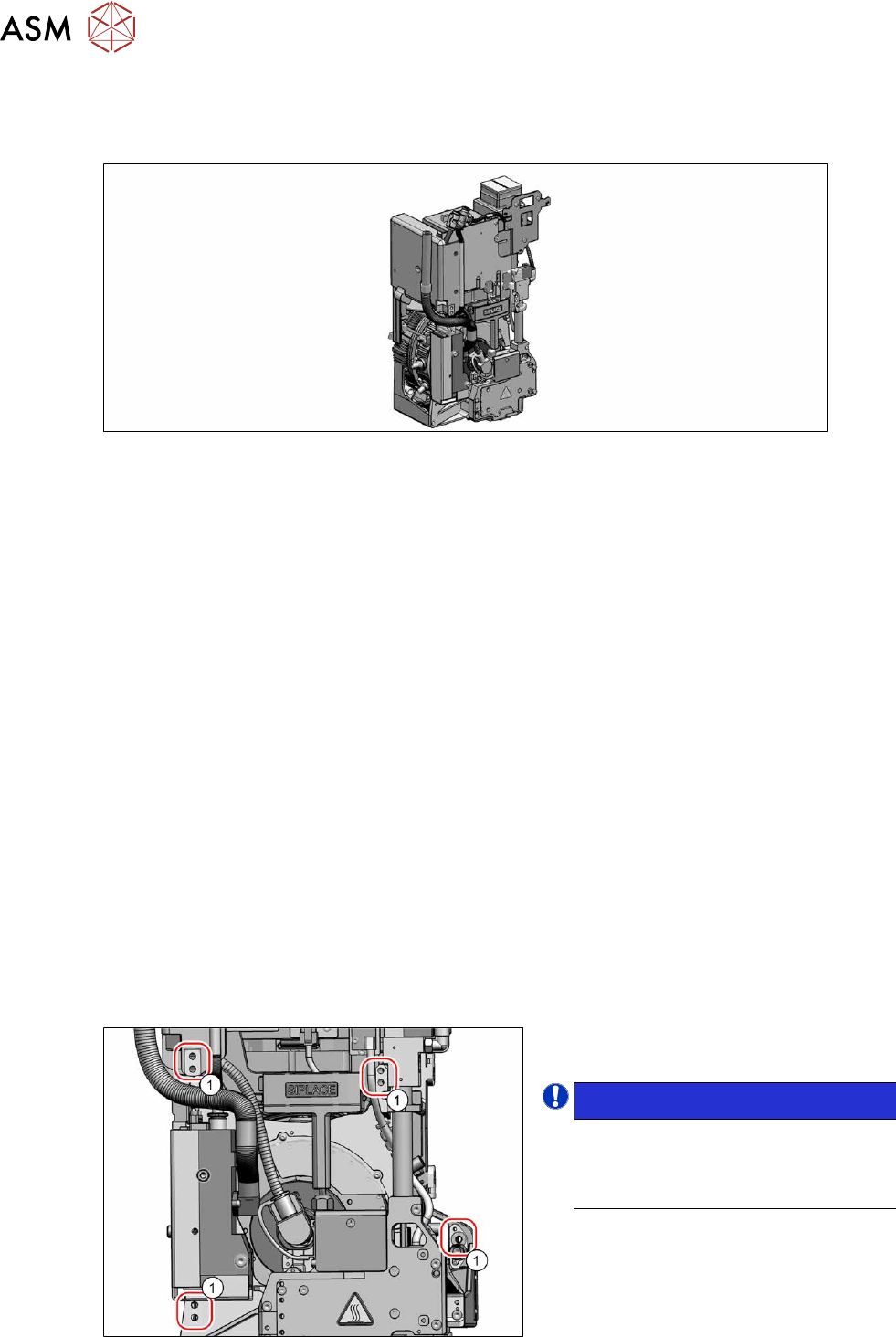
Fig.361: Overview (example of SIPLACE CPP head shown)
1. Fixture holes (two each, depends on in-
stallation height)
NOTICE!
The length of the exhaust air hose "Sil-
icon hose Di8 Da12 electrically con-
ductive 1m" [03006727Sxx] on the
SIPLACE CPP/CPP M is 316mm.
.