00198829-01_SM_X-Series-S_Hxxxx_EN.pdf - 第50页
3 Power supply 3.4 Power supply and transformer modules 50 Service Manual SIPLACE X-Series S (from Hxxxx) 01/2021 Execution / working procedure: ● The absence of voltage must be determined as closely as possible at the w…

3 Power supply
3.4 Power supply and transformer modules
Service Manual SIPLACE X-Series S (from Hxxxx) 01/2021 49
3.4.3 Checking For Absence of Voltage
DANGER
Power supply
The assembly contains energy-storing components (CAP and capacitors on the FDB
assembly)!
After switching off at the main switch or disconnecting from the main supply, hazardous
voltages are still present at some points of the assembly interior for a period of approx. five
minutes.
► Before performing any service work or disconnecting press-fit connections, make sure
that you check for absence of voltage - as described further below! Maintenance or re-
placement may only be performed when the assembly is de-energized.
► All press-fit connections for the CAP assembly and PS1 are of touch-proof design but
when connections are plugged in or unplugged while there is still residual voltage
(CAP capacitors are still charged, display lamps on PS1 or CAP still shine), this could
cause damage or destruction of these or other connected components!
Protective measures and rules of conduct
Tools / requirements:
●
The certified electrician or person instructed and trained in electrical matters must be familiar
with the voltage tester and with the particular details of the system (defined contact points for
determining absence of voltage).
●
Use certified voltage testers and phase testers with a certain fixed measuring range.
The use of universal and multiple measuring devices for determining the absence of voltages
is not permitted.
Only use two-pin voltage testers (DUSPOL) e.g. FLUKE T150 or T5-1000.
●
Knowledge of the user guide and all safety instructions specified by the voltage tester manu-
facturer is a requirement.
●
Observe the area of use for the measuring device (nominal voltage, protection class, voltage
type, switch-on period, temperature range, measurement category CAT IV
).
●
Check the external energy source of the measuring device.
●
Wear closely fitting and closed workwear.
●
Technicians working alone must be able to take any occurring risks into consideration and to
master them. In the event of any confusion, consult your specialist superior.
Preparation:
●
Use the voltage testers in accordance with their intended use. Inspect them for damage prior
to use. Damaged devices or cables may not be used and are to be reported immediately.
●
Before performing any measurements, test the voltage testers for functionality on a comparat-
ive voltage source or perform an integrated function test.
●
Ensure safe handling/safe workplace. Take sufficient space for movement and lighting into ac-
count.
●
Secure the area against proximity and hazard from persons.
●
Pay attention to any nearby exposed or active parts. Secure the measurement area, if neces-
sary.
3 Power supply
3.4 Power supply and transformer modules
50 Service Manual SIPLACE X-Series S (from Hxxxx) 01/2021
Execution / working procedure:
●
The absence of voltage must be determined as closely as possible at the workplace, at all
pins, by a certified electrician or person specially instructed in electrics.
●
Make sure you select the correct measurement area or workplace.
●
Only touch the measuring device by the insulated test handles (up to inside handles). Do not
touch the test electrodes (testing tips).
●
During testing, take hold of the voltage tester fully (DUSPOL). Press the testing tips manually
against the part to be measured e.g. FLUKE T150 or T5-1000.
●
The contact electrodes or testing tips of voltage testers must always have a conductive elec-
trical contact with the system part to be tested.
●
The testing tips must always be securely clamped or plugged into the part to be measured.
Measuring lines must be well connected to the phase tester.
●
Ensure a secured and concentrated attachment and removal of the measuring device tips or
testing pins.
●
Use auxiliary clamps (banana plugs, crocodile clips, spider legs, measuring jacks) with suit-
able voltage and clamping reliability.
●
Read the measurement rotary field display at eye level and with an uninhibited view. Watch
out for reflections and mirroring on the measurement scale.
Measuring device for determining absence of voltage
DANGER
Only use the DUSPOL voltage tester!
Universal or multiple measuring devices for determining the absence of voltage are not
permitted.
The reason for this is that the correct voltage type (DC or AC) and the correct voltage range
need to be set in advance.
The direct current to be measured: 300VDC can cause serious or lethal injuries if the
measuring device is incorrectly set or defective.
► For this reason, only use the two-pin voltage tester (DUSPOL)!
Fig.47: Voltage tester of type "Fluke T-150".
Example:
The figure shows a two-pin voltage tester of
type "Fluke T-150".
This device can be procured world-wide via
the internet or from your specialist dealer.
Similar devices from other manufacturers
may also be used.
3 Power supply
3.4 Power supply and transformer modules
Service Manual SIPLACE X-Series S (from Hxxxx) 01/2021 51
Procedure for determining absence of voltage
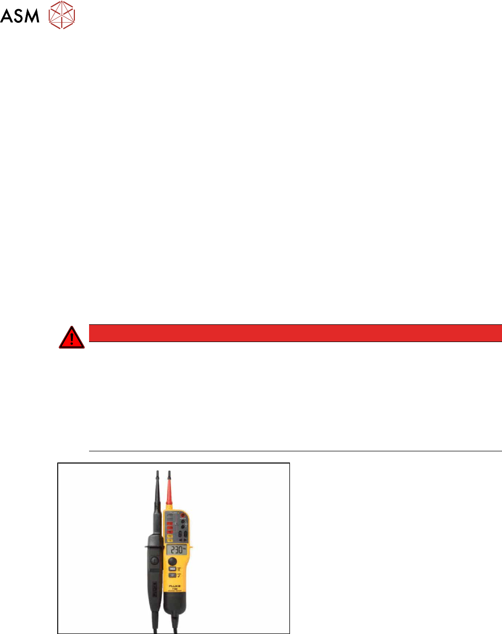
Ensure correct handling of the voltage tester:
●
The measuring device may only be touched by the insulated test handles (up to inside
handles) and the test electrodes (testing tips) may not be touched!
Fig.48: Correct and incorrect handling of the voltage tester
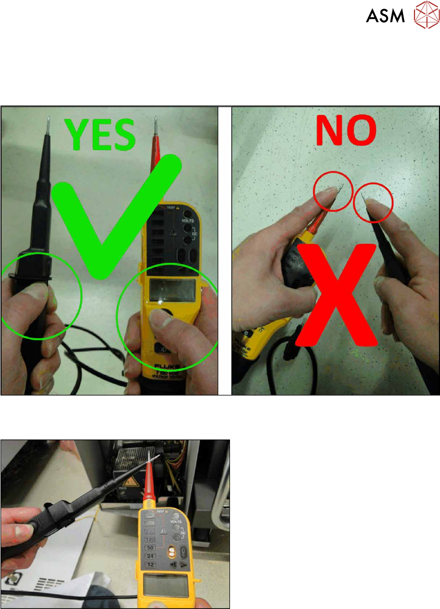
Determining voltage tester functionality
Fig.49: Performing a self-test of the voltage tester
First perform a self-test of the voltage tester.
To do this, place the two testing tips to-
gether.
The voltage tester will be checked for
throughput and the LED throughput display
must be visible and an audio signal must be
heard.
After approx. three seconds you can discon-
nect the two testing tips again.