00198829-01_SM_X-Series-S_Hxxxx_EN.pdf - 第363页
9 Component feeding 9.6 Smart Pin Support Service Manual SIPLACE X-Series S (from Hxxxx) 01/2021 363 9.6.5.1 Control board SPS The control board SPS is fitted to the pin picker of the Smart Pin Support option. Fig.521: …
9 Component feeding
9.6 Smart Pin Support
362 Service Manual SIPLACE X-Series S (from Hxxxx) 01/2021
9.6.5 Replacing the control board
Parts, equipment and tools
●
Control board SPS [03089614Sxx]
●
Assembly instructions "Smart Pin Support" for SIPLACE X‑SeriesS [DEEN:00197394‑xx]
Overview
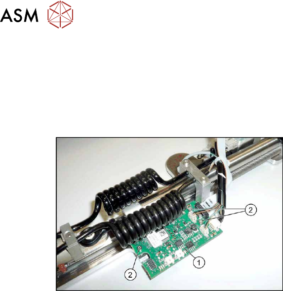
Fig.520: Control board
1. Control board
2. Three fastening screws for the control
board
Removal
► Switch off the machine, disconnect it from the power supply and secure it to prevent
unauthorized reactivation.
1.2 "Preparatory work..." [}16]
► Remove the Pin Picker.
9.6.1 "Replacing the Pin Picker Assembly" [}357]
► Unplug the electrical connections. Mark their positions, to make clear assignment easier later
on.
► Remove the three screws fastening the control board. Make sure that you do not lose the cor-
responding bushings on the back.
Installation
Follow the removal instructions in reverse order for installation. Also observe the following instruc-
tions:
► Perform a function check. Check whether the Pin Picker is recognized by the software and
also check the LEDs.
► See also 9.6.5.1 "Control board SPS" [}363]
9 Component feeding
9.6 Smart Pin Support
Service Manual SIPLACE X-Series S (from Hxxxx) 01/2021 363
9.6.5.1 Control board SPS
The control board SPS is fitted to the pin picker of the Smart Pin Support option.
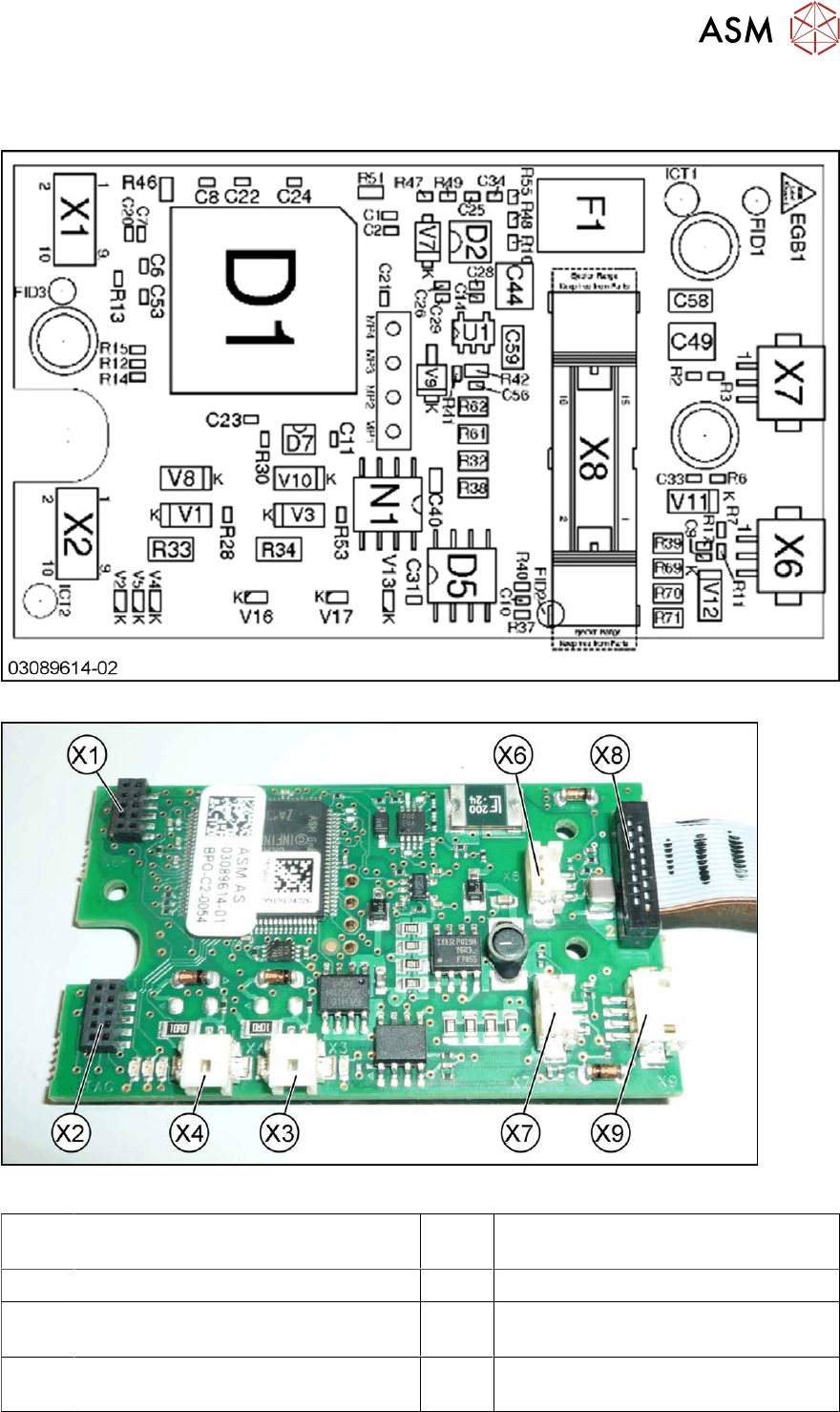
Fig.521: Control board – board overview
Fig.522: Control board – connections [03089614-01]
X1,X2 Diagnosis / Test connector X3,X4 Diagnosis / Test connector (not used
in FS02)
X5 Magnet (rear side) X6 Proximity switch down
X7 Proximity switch up X8 Connection to head interface
(FS01: ribbon cable on the rear side)
X9 Valves lifting cylinder and cleaning
pulse
On the back of the board:
Power electromagnet connection
9 Component feeding
9.6 Smart Pin Support
364 Service Manual SIPLACE X-Series S (from Hxxxx) 01/2021
9.6.6 Replacing the swivel head
Parts, equipment and tools
●
Swivel head with inner thread KBRM-03 [03088119Sxx]
●
Assembly instructions "Smart Pin Support" for SIPLACE X‑SeriesS [DEEN:00197394‑xx]
Overview
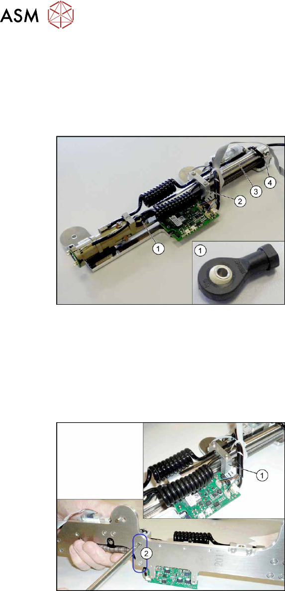
Fig.523: Swivel head
1. Swivel head
2. Pneumatic cylinder guidance
3. Pneumatic cylinder
4. Pneumatic connection for pneumatic
cylinder
Removal
► Switch off the machine, disconnect it from the power supply and secure it to prevent
unauthorized reactivation.
1.2 "Preparatory work..." [}16]
► Remove the Pin Picker.
9.6.1 "Replacing the Pin Picker Assembly" [}357]
Fig.524: Screws fastening the guide
► Remove the two screws(2) fastening
the pneumatic cylinder guidance(1)
.
► For better access, you may want to un-
plug the electrical connections to the
control board. In this case, note the
connector positions to make clear as-
signment easier later on.
► Remove the screw fastening the swivel head.
► You may find it helpful to unplug the pneumatic connection on the pneumatic cylinder so that
you can move the pneumatic cylinder more easily.
► Remove the swivel head from the pneumatic cylinder.
Installation
Follow the removal instructions in reverse order for installation. Also observe the following instructions:
► Check the linear guide travel path. The linear guide must be easy to move along the whole length.
► Check that the sensors switch properly. The switch tag of the linear guide must have approx.
1 mm space to the trolley.