00198829-01_SM_X-Series-S_Hxxxx_EN.pdf - 第288页
9 Component feeding 9.1 Cutter 288 Service Manual SIPLACE X-Series S (from Hxxxx) 01/2021 9.1.5 Replacing the Metal Buffer/Spacer Distance Piece Parts Fig.387: Spacer and metal buffer 03007432‑xx Spacer 00329209‑xx Meta…
9 Component feeding
9.1 Cutter
Service Manual SIPLACE X-Series S (from Hxxxx) 01/2021 287
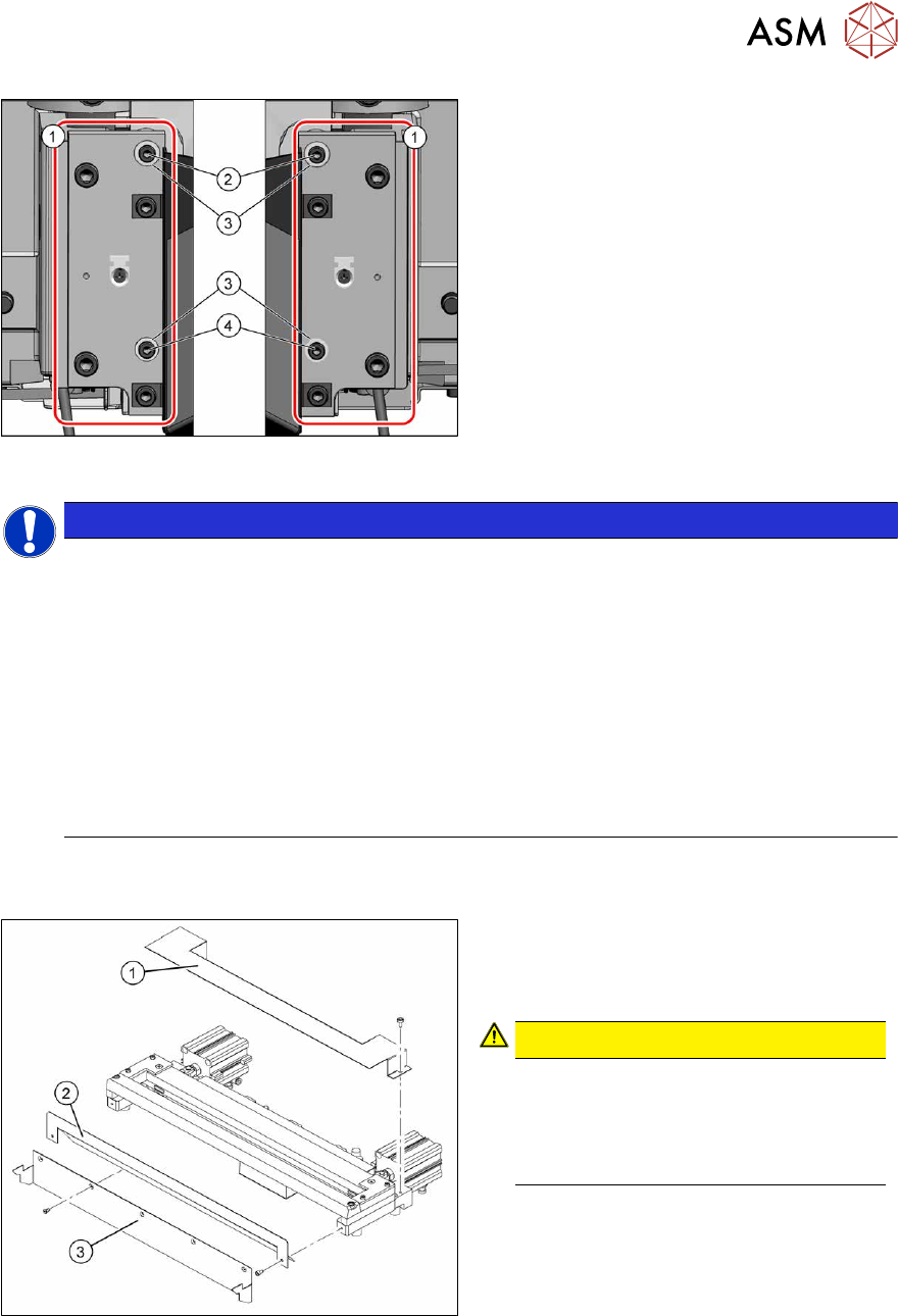
Fig.385: Fastening of new holder (example of
SIPLACEX4S shown)
1. 2x holder [03008869‑03]
2. 2x ISO4762-M4x16-A2-70
[03042507‑xx]
3. 4x serrated lock washers M4-
FST.1.4401 [03047857‑xx]
4. 2x ISO4762-M4x30-A2-70
[03042557‑xx]
To fit the holder, proceed as follows(1):
NOTICE
The spring rings used to date are no longer permissible. The mount must therefore
be changed.
► Only use the serrated lock washers [03047857‑xx] to fasten the rail [03008869‑03].
► Use the following screws to fasten the brackets:
2x ISO4762-M4x16-A2-70 [03042507-xx] and 2x ISO4762-M4x30-A2-70 [03042557-xx]
► If longer or shorter screws are used or if the serrated lock washers are missing, the
metal buffers will be subjected to excess strain and the screws could work loose. In
this case, the cutter fixtures are no longer reliable.
► Secure the screws with Loctite 243.
► Used screw clamps to protect the metal buffers from torsion during tightening.
► The maximum tightening torque is 2 Nm.
► Carefully lift the cutter onto the spacer sleeves. Use the spacer disks if provided.
► Tighten all four fastening screws.
Fig.386: Cutter (using example of X-Series)
1. Cover plate
2. Baffle plate
3. Protective plate
CAUTION!
There is a risk of injuring yourself on the
cutting edge of the blades.
For this reason, the deflector plate,
cover plate and protective sheet must
be left mounted!
.
► Move the cutter into its installation position, using the support/chair for assistance.
► Carefully lift the cutter into the planned position.
► Tighten all four fastening screws.
► Reconnect to the electrical and compressed air systems.
► Fit the waste tape container.
Follow the removal instructions in reverse order for further installation.
9 Component feeding
9.1 Cutter
288 Service Manual SIPLACE X-Series S (from Hxxxx) 01/2021
9.1.5 Replacing the Metal Buffer/Spacer Distance Piece
Parts
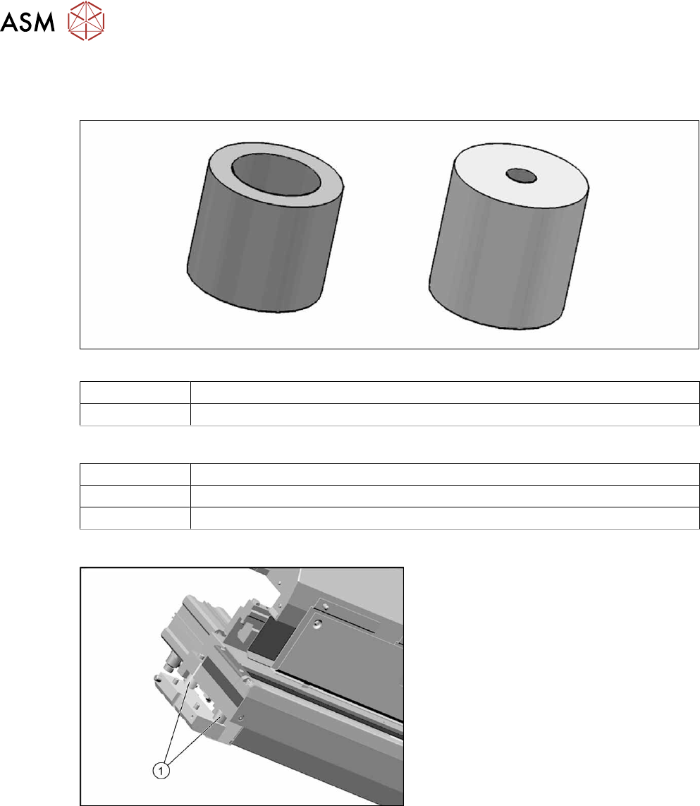
Fig.387: Spacer and metal buffer
03007432‑xx Spacer
00329209‑xx Metal buffer M4.65 Shore
Equipment and tools
00353832-xx Allen key set
Wire cutters
Cable tie
Overview
Fig.388: Metal buffer and spacer distance piece on cutter
1. Metal buffer and spacer (two on each
side)
The metal butters absorb the cutting
vibration to the machine base.
9 Component feeding
9.1 Cutter
Service Manual SIPLACE X-Series S (from Hxxxx) 01/2021 289
Removal
NOTICE
Same procedure
The removal and installation is described below using the example of the metal buffer. The
removal and installation of the spacer is the same as that for the metal buffer.
► Switch off the machine, disconnect it from the power supply and secure it to prevent
unauthorized reactivation.
1.2 "Preparatory work..." [}16]
► Remove the cutter from the machine.
9.1.4 "Replacing the Cutter on the COT Insert [03066690-xx]" [}285]
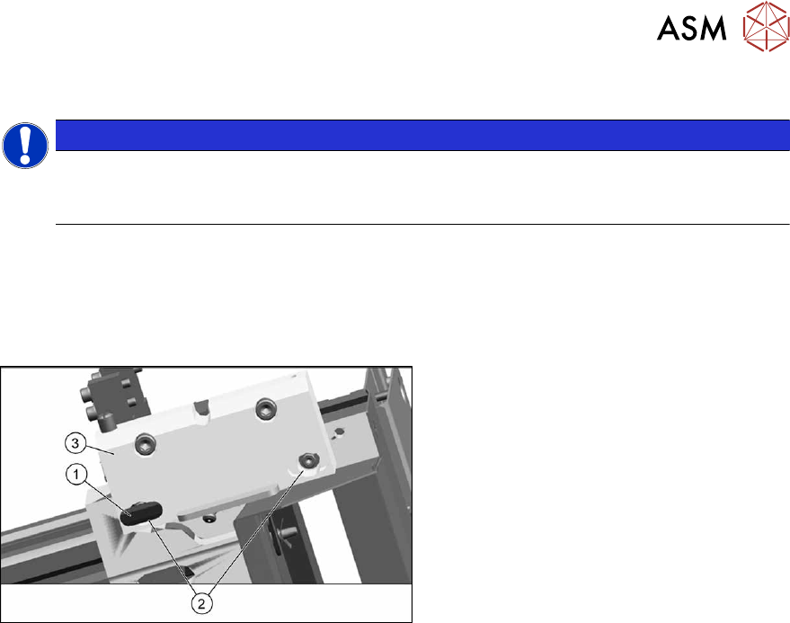
Fig.389: Removing the metal buffer
► Remove the plastic cover(1).
► Take out the screws(2).
► Remove the complete mounting
strip(3)
.
► Remove the metal buffer.
Installation
Follow the removal instructions in reverse order for further installation.