00198829-01_SM_X-Series-S_Hxxxx_EN.pdf - 第219页
7 Conveyor 7.8 Laser light barriers, fiber optic cable and PCB sensors Service Manual SIPLACE X-Series S (from Hxxxx) 01/2021 219 7.8.2 Replacing the Laser Light Barrier Cable Parts, equipment and tools Select the correc…
7 Conveyor
7.8 Laser light barriers, fiber optic cable and PCB sensors
218 Service Manual SIPLACE X-Series S (from Hxxxx) 01/2021
Removal
CAUTION
Move the conveyor sides carefully!
The clamping and guide rails are a key stabilizing element for the conveyor side, which is
then less stable once they have been removed.
► Move the opened conveyor sides very carefully.
► Make sure that the sides are always pushed equally on the left and right.
► Make sure that you do not distort the sides.
► Switch off the machine, disconnect it from the power supply and secure it to prevent
unauthorized reactivation.
1.2 "Preparatory work..." [}16]
► Dismantle the two clamping rails/belt guides on the transmitter/receiver.
7.7.3 "Replacing the Clamping Rail/Belt Guidance" [}210]
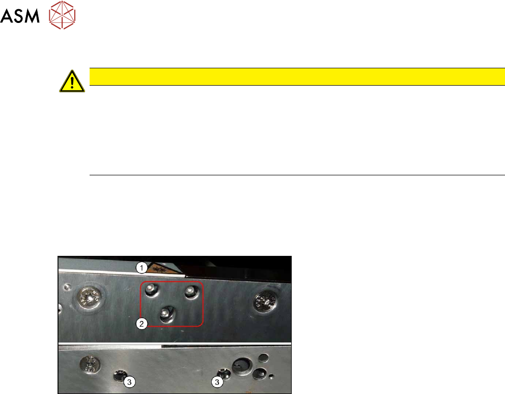
Fig.286: Fastening screws
The transmitters are always near the laser
warning labels(1)
. The receivers are always
on the opposite side walls.
► Transmitter: Remove the three fasten-
ing screws(2)
. Make sure that no parts
fall into the conveyor side wall.
► Receiver: Remove the two fastening
screws (3)
. Make sure that no parts fall
into the conveyor side wall.
► Unplug the electrical connection.
Installation
Follow the removal instructions in reverse order for installation. Also observe the following instruc-
tions:
► Reconnect the transmitter/receiver before installation.
► Make sure that all the other cables in the conveyor rail are run under the transmitter/receiver.
There is a particular lack of space at the transmitters.
If needed, the screw behind the housing can be loosened and replaced with a shorter screw
(8mm).
The screws could also be in the way of the idler pulleys.
See the following diagrams for details.
► Use the bushing for the bottom screw. This screw is used to fix the sensor.
The two upper screws are used to adjust the laser beam.
► The transmitters are fixed hand-tight with the lower screw and adjusted with the top two
screws.
► Check the setting for the transmitter/receiver and correct if necessary.
7.8.3 "Checking the laser light barrier" [}222]
7.8.4 "Correcting the Laser Light Barrier Setting" [}225]
► Teach the PCB sensors using the station software.
7.8.9
"Teaching the PCB sensors (SW70x)" [}240]
7 Conveyor
7.8 Laser light barriers, fiber optic cable and PCB sensors
Service Manual SIPLACE X-Series S (from Hxxxx) 01/2021 219
7.8.2 Replacing the Laser Light Barrier Cable
Parts, equipment and tools
Select the correct spare cable:
Motor cable
Part to be replaced Correct spare part
[03088532‑xx] Motor cable belt motor input lane-1 L=730 mm Motor cable belt mo-
tor input lane 2
L=2170 mm
[03088863‑xx]
[03088533‑xx] Motor cable belt motor placement position 1 lane 1 L=1640 mm
[03088534‑xx] Motor cable belt motor intermediate position lane 1 L=1260mm
[03088536‑xx] Motor cable belt motor placement position 2 lane 1 L=1650 mm
[03088537‑xx] Motor cable belt motor output lane 1 L=730 mm
[03088538‑xx] Motor cable belt motor input lane 2 L=730 mm
[03088541‑xx] Motor cable belt motor placement position 1 lane 2 L=1650 mm
[03088542‑xx] Motor cable belt motor intermediate position lane 2 L=1490mm
[03088543‑xx] Motor cable belt motor placement position 2lane 2 L=1650 mm
[03088544‑xx] Motor cable belt motor output lane 2 L=730 mm
Sensor cable
Part to be replaced Correct spare part
[03088545‑xx] Sensor cable belt motor input lane 1 L=760 mm Sensor cable belt mo-
tor input lane 2
L=2180 mm
[03088871‑xx]
[03088547‑xx] Sensor cable belt motor placement position 1 lane 1
L=1680 mm
[03088549‑xx] Sensor cable belt motor intermediate position lane 1
L=1500 mm
[03088551‑xx] Sensor cable belt motor placement position 2 lane 1
L=1680 mm
[03088552‑xx] Sensor cable belt motor output lane 1 L=760 mm
[03088553‑xx] Sensor cable belt motor input lane 2 L=760 mm
[03088554‑xx] Sensor cable belt motor placement position 1 lane 2
L=1680 mm
[03088555‑xx] Sensor cable belt motor intermediate position lane 2
L=1220 mm
[03088556‑xx] Sensor cable belt motor placement position 2 lane 2
L=1690 mm
[03088557‑xx] Sensor cable belt motor output lane 2 L=760 mm
[03092519‑xx] Sensor cable W51 laser side panel C2 L=1530 mm Sensor cable W46
laser side panel C1
L=1630 mm
[03092514‑xx]
[03088491‑xx] Sensor cable W30 sensor 1 side panel B1 L=1220 mm Sensor cable W41
sensor 1 side panel
B2 L=2170
[03088495‑xx]
[03088492‑xx] sensor cable W31 sensor 2 side panel B1 L=1590 mm
[03088496‑xx] sensor cable W42 sensor 2 side panel B2 L=1660 mm
7 Conveyor
7.8 Laser light barriers, fiber optic cable and PCB sensors
220 Service Manual SIPLACE X-Series S (from Hxxxx) 01/2021
Other cables
Part to be replaced Correct spare part
[03092517‑xx] Cable W49 side panel D1 sensor LLB1 L=1360 mm Cable PCB centering
receiver LLB2
L=1850 mm
[03088522‑xx]
[03092518‑xx] Cable W50 side panel D1 sensor LLB2 L=1020 mm
[03093772‑xx] Cable W69 side panel D2 sensor LLB1 L=950 mm
[03093773‑xx] Cable W70 side panel D2 sensor LLB2 L=1420 mm
[03088490‑xx] Cable W21 side panel A1 laser LLB1, LLB2 L=940 mm Cable PCB centering
LLS1, LLS2, L=1860
mm [03088856‑xx]
[03088493‑xx] Cable W43 side panel A2 laser LLB1, LLB2 L=1360 mm
NOTICE
Labeling the cable
► Label the new cable identically to the cable which is to be replaced. If the cable is too
long, stow the excess length in the conveyor base, near the connection. Fix the cables
with a cable tie, where necessary.
Overview
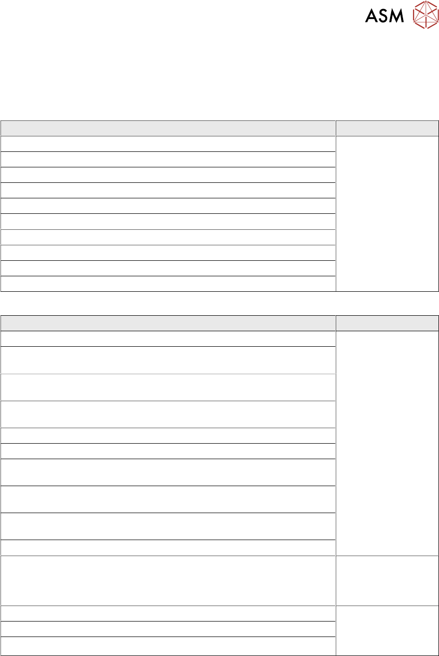
Fig.287: Overview of conveyor controls
The cables for the laser light barriers are
either connected directly to the conveyor
controls(1)
or to the input or output area(2)
of the conveyor.
For details of the conveyor control, see
7.9.1.1
"Conveyor control TSP420" [}242].
Removal
► Switch off the machine, disconnect it from the power supply and secure it to prevent
unauthorized reactivation.
1.2 "Preparatory work..." [}16]
CAUTION
Move the conveyor sides carefully!
The clamping and guide rails are a key stabilizing element for the conveyor side, which is
then less stable once they have been removed.
► Move the opened conveyor sides very carefully.
► Make sure that the sides are always pushed equally on the left and right.
► Make sure that you do not distort the sides.
CAUTION
Make a note of the order in which the cables are run!
The room in the side walls is limited. Therefore, make sure that no cables are crossed over,
particularly in the output area, from the trailing cable to the laser light barrier.
Make a note of the order in which the cables are run in the side panel, so that you can run
them neatly and correctly again later on.