00198829-01_SM_X-Series-S_Hxxxx_EN.pdf - 第51页
3 Power supply 3.4 Power supply and transformer modules Service Manual SIPLACE X-Series S (from Hxxxx) 01/2021 51 Procedure for determining absence of voltage Ensure correct handling of the voltage tester: ● The measurin…
3 Power supply
3.4 Power supply and transformer modules
50 Service Manual SIPLACE X-Series S (from Hxxxx) 01/2021
Execution / working procedure:
●
The absence of voltage must be determined as closely as possible at the workplace, at all
pins, by a certified electrician or person specially instructed in electrics.
●
Make sure you select the correct measurement area or workplace.
●
Only touch the measuring device by the insulated test handles (up to inside handles). Do not
touch the test electrodes (testing tips).
●
During testing, take hold of the voltage tester fully (DUSPOL). Press the testing tips manually
against the part to be measured e.g. FLUKE T150 or T5-1000.
●
The contact electrodes or testing tips of voltage testers must always have a conductive elec-
trical contact with the system part to be tested.
●
The testing tips must always be securely clamped or plugged into the part to be measured.
Measuring lines must be well connected to the phase tester.
●
Ensure a secured and concentrated attachment and removal of the measuring device tips or
testing pins.
●
Use auxiliary clamps (banana plugs, crocodile clips, spider legs, measuring jacks) with suit-
able voltage and clamping reliability.
●
Read the measurement rotary field display at eye level and with an uninhibited view. Watch
out for reflections and mirroring on the measurement scale.
Measuring device for determining absence of voltage
DANGER
Only use the DUSPOL voltage tester!
Universal or multiple measuring devices for determining the absence of voltage are not
permitted.
The reason for this is that the correct voltage type (DC or AC) and the correct voltage range
need to be set in advance.
The direct current to be measured: 300VDC can cause serious or lethal injuries if the
measuring device is incorrectly set or defective.
► For this reason, only use the two-pin voltage tester (DUSPOL)!
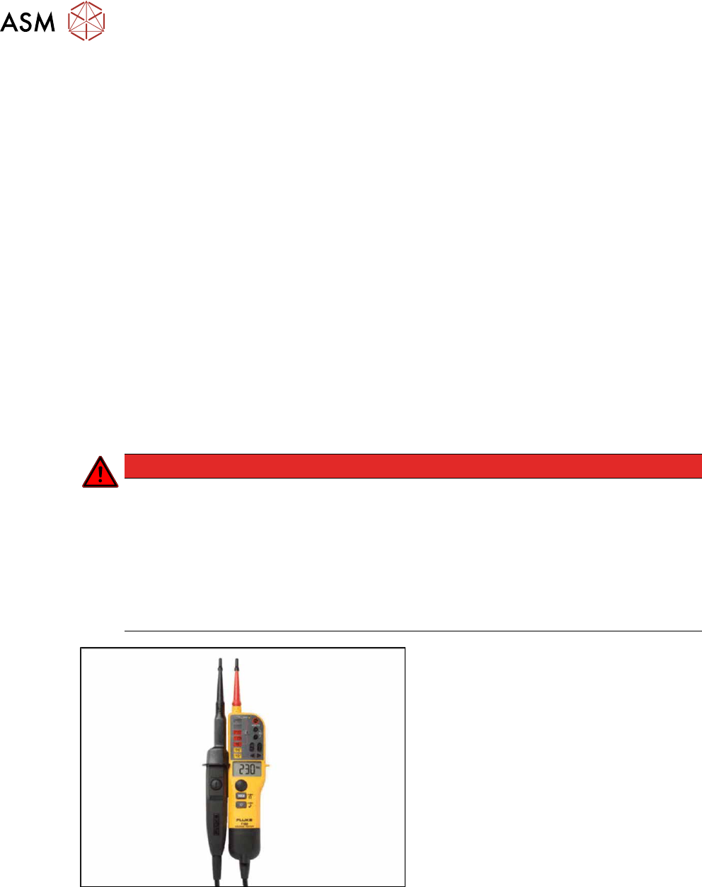
Fig.47: Voltage tester of type "Fluke T-150".
Example:
The figure shows a two-pin voltage tester of
type "Fluke T-150".
This device can be procured world-wide via
the internet or from your specialist dealer.
Similar devices from other manufacturers
may also be used.
3 Power supply
3.4 Power supply and transformer modules
Service Manual SIPLACE X-Series S (from Hxxxx) 01/2021 51
Procedure for determining absence of voltage
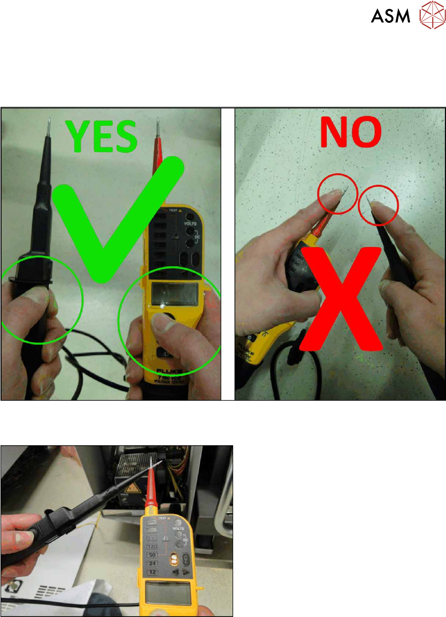
Ensure correct handling of the voltage tester:
●
The measuring device may only be touched by the insulated test handles (up to inside
handles) and the test electrodes (testing tips) may not be touched!
Fig.48: Correct and incorrect handling of the voltage tester
Determining voltage tester functionality
Fig.49: Performing a self-test of the voltage tester
First perform a self-test of the voltage tester.
To do this, place the two testing tips to-
gether.
The voltage tester will be checked for
throughput and the LED throughput display
must be visible and an audio signal must be
heard.
After approx. three seconds you can discon-
nect the two testing tips again.
3 Power supply
3.4 Power supply and transformer modules
52 Service Manual SIPLACE X-Series S (from Hxxxx) 01/2021
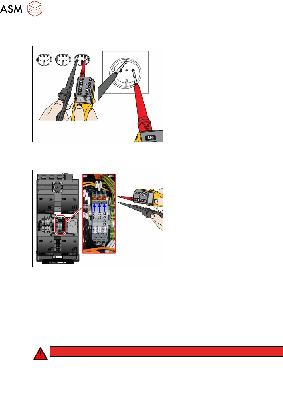
Measurement with known reference voltage
To conclude the self-test, check the voltage tester with a known reference voltage.
Fig.50: Test with reference voltage
You can use the service socket (if present)
on the power supply (disabled with "110V
option") or any other electrical socket.
Measure the voltage present between the
pins and at PE (ground).
Measuring the voltage absence directly after switching machine off
Fig.51: Check voltages
When the machine has been switched off,
the full voltage is still present at the meas-
urement points X303 and X304.
Measurement is always performed at the ref-
erence point (GND)!
●
X303 – X305 GND: 300+/‑10V OUT
●
X304 –X305 GND: 300+/‑10V
Test 300V IN_X303-X305:
Voltage currently present
Test 300V OUT_X304-X305:
LED display Output 1 at AC/DC converter
Green: Voltage over 220V
The power pack shows an LED display for output 1 > 220 V in green, which means that the voltage
is still over 220 V!
DANGER
Dangerous voltages
The power supply contains energy-storing components (CAP and capacitors on the FDB
assembly)!
After switching off at the main switch or disconnecting from the main supply, hazardous
voltages are still present at some points of the assembly interior for a period of approx. five
minutes.
► Always observe the maintenance intervals!
The following figure explains the LED status of power packs PS1 and PS2 (300VDC):