00198829-01_SM_X-Series-S_Hxxxx_EN.pdf - 第247页
7 Conveyor 7.10 Conveyor sides Service Manual SIPLACE X-Series S (from Hxxxx) 01/2021 247 ► Move the conveyor side into the required position. ► Insert the screws loosely. Press the side so that it engages with the screw…
7 Conveyor
7.10 Conveyor sides
246 Service Manual SIPLACE X-Series S (from Hxxxx) 01/2021
7.10 Conveyor sides
7.10.1 Setting the Fixed Conveyor Side
7.10.1.1 Setting the Fixed Conveyor Side on Single Conveyors
CAUTION
Moving the conveyor sides
► The conveyor sides are highly sensitive. Move them very carefully and evenly. Take
special care not to distort the conveyor sides.
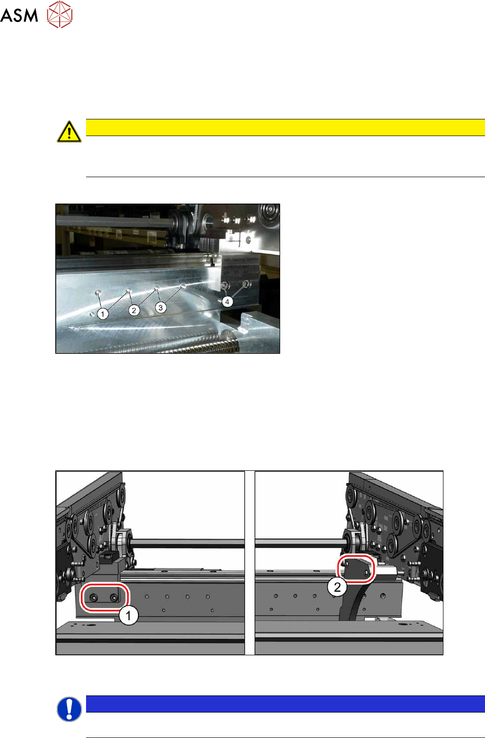
Overview
Fig.324: Overview of side wall positions
1. Position 231.0 mm
Max. PCB width: 460mm
2. Position 256.0 mm
Max. PCB width: 560mm
3. Position 281.0 mm
Max. PCB width: 560mm
4. Position 344.0 mm
Max. PCB width: 685mm
The conveyor side is fixed with two fastening
screws each point from (1)
to (4).
Setting
► Use the software to move the conveyor sides into a position which allows you best access.
► Switch off the machine, disconnect it from the power supply and secure it to prevent
unauthorized reactivation.
1.2 "Preparatory work..." [}16]
► Always perform the following three steps immediately at the three holders.
Fig.325: Setting the conveyor side position
► Remove the screws (1) fastening the conveyor side (two screws per holder).
NOTICE
You can also loosen two screws on the connection between the side wall and the flange, to
prevent distortion during movement. The side wall is otherwise very difficult to move.
7 Conveyor
7.10 Conveyor sides
Service Manual SIPLACE X-Series S (from Hxxxx) 01/2021 247
► Move the conveyor side into the required position.
► Insert the screws loosely. Press the side so that it engages with the screw holes either in a
forwards or backwards inclination (against all three holders in the same direction). Tighten the
fastening screws in the new position.
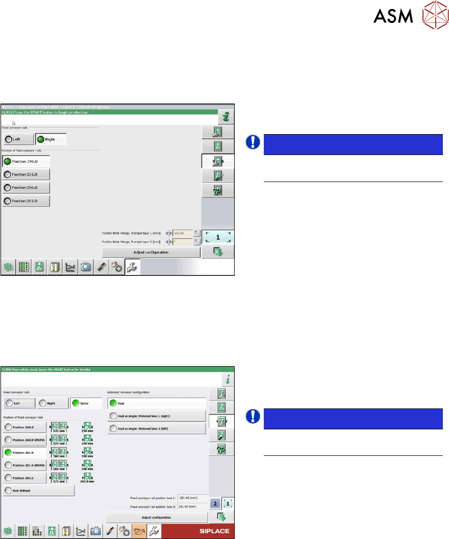
Fig.326: Setting the conveyor side
► In the software set the fixed conveyor
side and the position.
NOTICE!
This menu is accessible from operator
level Service (customer)!
.
7.10.1.2 Setting the Fixed Conveyor Side on Dual Conveyors
The fixed conveyor edge is always set with the software for dual conveyors.
Setting
Fig.327: Setting the conveyor side position
► In the software set the fixed conveyor
side and the position.
Conveyor Sides - Settings
NOTICE!
This menu is accessible from operator
level Service (customer)!
.
7 Conveyor
7.10 Conveyor sides
248 Service Manual SIPLACE X-Series S (from Hxxxx) 01/2021
7.10.2 Setting the Parallelism of the Conveyor Sides and Adjustment Units
7.10.2.1 Setting the parallelism of the sides on the single conveyor
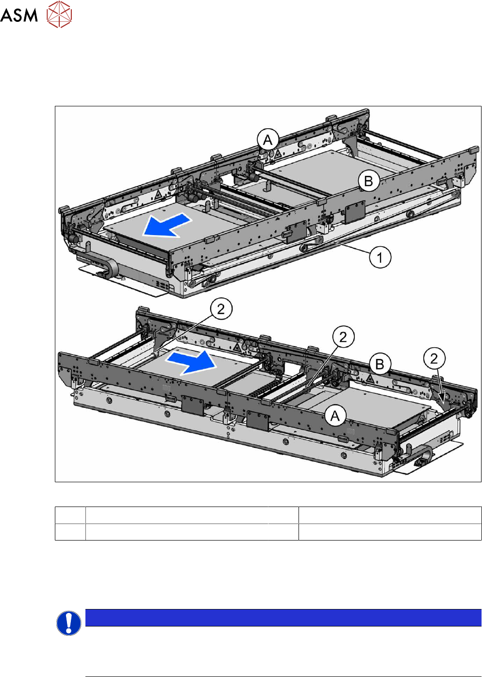
Overview
Fig.328: Overview of width adjustment
A Conveyor side A (fixed) B Conveyor side B (moveable)
1 Toothed belt (width adjustment) 2 Width adjustment (flange and spindle)
Setting
► This setting is identical for the dual conveyor. For more information about this, read section
7.10.2.2
"Setting the parallelism of the conveyor side walls and adjustment units for dual con-
veyors" [}249].
NOTICE
Procedure identical to that for adjustment units on dual conveyor
In a single conveyor, the movable conveyor side is directly connected with the recirculating
ball screws of the width adjustment. This is set via the toothed belt. This must jump one or
more teeth via the relevant idler pulleys.