00198829-01_SM_X-Series-S_Hxxxx_EN.pdf - 第334页
9 Component feeding 9.3 X-Series Component Trolley 334 Service Manual SIPLACE X-Series S (from Hxxxx) 01/2021 9.3.5 Replacing the bearing assembly Parts Fig.470: Bearing assembly 03103947-xx Bearing assembly NOTICE Repl…
9 Component feeding
9.3 X-Series Component Trolley
Service Manual SIPLACE X-Series S (from Hxxxx) 01/2021 333
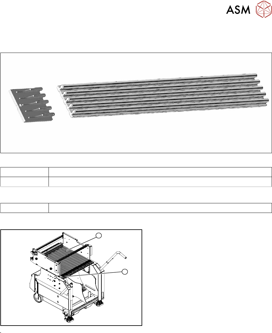
9.3.4 Replacing the Guide Profile/Entering Guide Feeder
Parts
Fig.468: Entering guide and guide profile
03002898-xx Short guide profile
03039368-xx Feeder entering guide
Equipment and tools
00353832-xx Allen key set
Overview
1
2
Fig.469: Guide profiles on component trolley
1. Short guide profile
2. Feeder entering guide
The short guide profiles are fixed from
above with one screw each.
The feeder entering guide is screwed into
place from below.
9 Component feeding
9.3 X-Series Component Trolley
334 Service Manual SIPLACE X-Series S (from Hxxxx) 01/2021
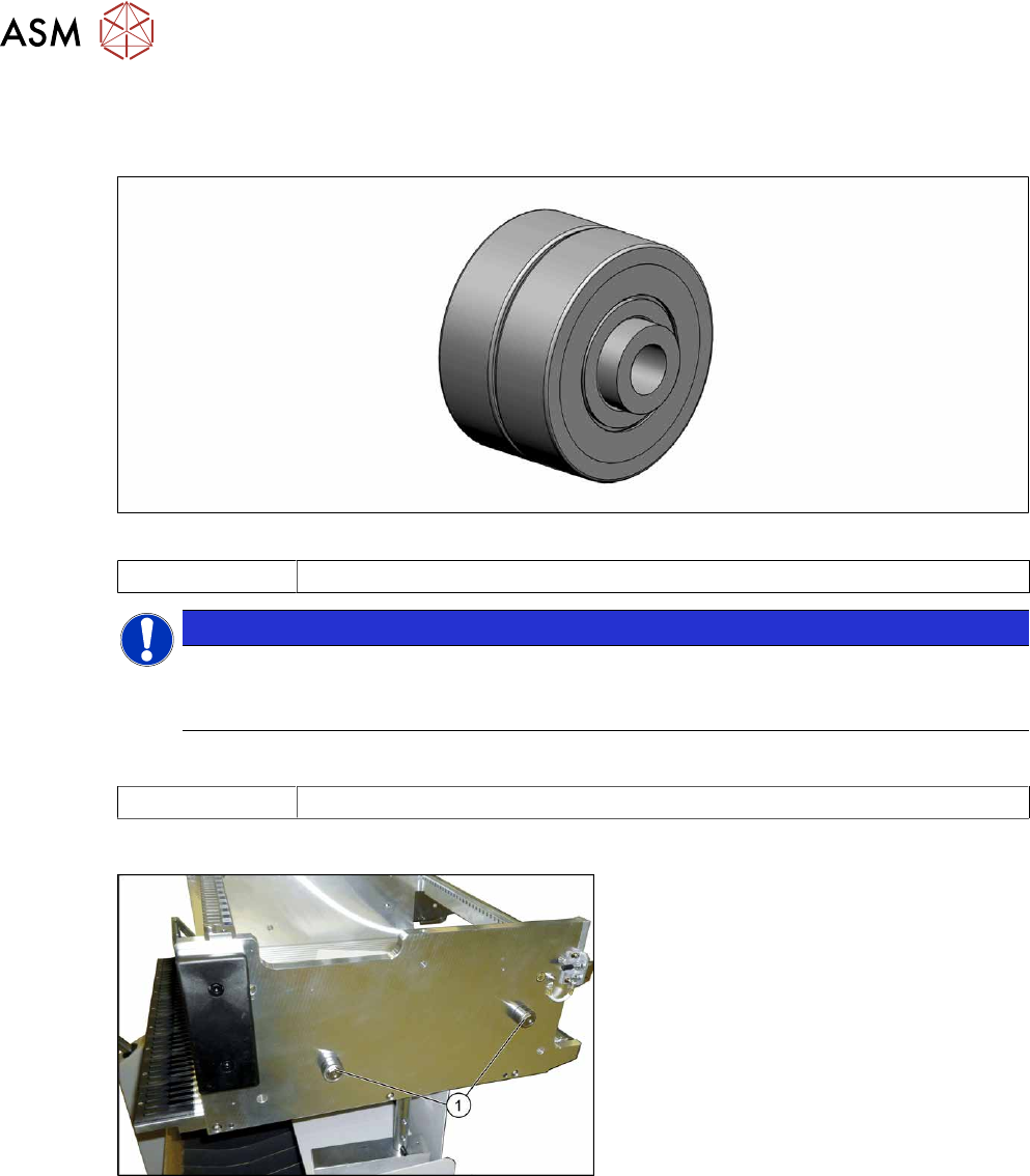
9.3.5 Replacing the bearing assembly
Parts
Fig.470: Bearing assembly
03103947-xx Bearing assembly
NOTICE
Replacing all sleeves
We recommend that you always replace all bearing assemblies belonging to a changeover
table at the same time.
Tools
00334892-xx Loctite 243
Overview
Fig.471: Centering sleeves
1. Bearing assembly (four per table)
Removal
► Remove the screw fastening the bearing assembly and then remove the bearing assembly.
Installation
Follow the removal instructions in reverse order for installation. Also observe the following instruc-
tions:
► Secure the screw with Loctite243.
9 Component feeding
9.3 X-Series Component Trolley
Service Manual SIPLACE X-Series S (from Hxxxx) 01/2021 335
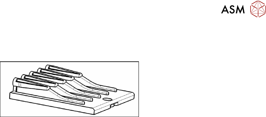
9.3.6 Replacing the insert feeder
Parts, equipment and tools
Select the right insert feeder:
Fig.472: Insert feeder [03002898-xx]
Insert feeder [03002898-xx]
Suitable for:
●
SIPLACE X-series component trolley
●
Component trolley SIPLACE SX1/SX2
(30 or 60 tracks)
●
Manual table SIPLACE X‑SeriesS
Removal
► Move the component trolley out of the machine.
► Remove the screw fastening the guide profile and then remove the guide profile.
Installation
Follow the removal instructions in reverse order for installation. Observe the following note:
► Make sure that the insert is aligned properly with the guidance behind it. You must be able to
push feeder modules into the feeder location without edge interference.