00198829-01_SM_X-Series-S_Hxxxx_EN.pdf - 第286页
9 Component feeding 9.1 Cutter 286 Service Manual SIPLACE X-Series S (from Hxxxx) 01/2021 WARNING Risk of injury when releasing the fixtures! The cutter is only held by the fastening screws and is not supported by other …
9 Component feeding
9.1 Cutter
Service Manual SIPLACE X-Series S (from Hxxxx) 01/2021 285
Removal
► Remove the screws fastening the used tape chute.
► Take the used tape chute down and out of the machine.
CAUTION
Risk of cutting
The cutter is located under the tape channel. The blades there have very sharp edges.
► Do not reach into the cutter and make sure that it is never freely accessible.
Installation
► Follow the removal instructions in reverse order for installation.
9.1.4 Replacing the Cutter on the COT Insert [03066690-xx]
Parts, equipment and tools
●
Cutter, pneumatic SIPLACE HF/X-Series [03066690-xx]
●
Screw clamp
●
For additional work to the cutter:
Two large parallel clamps and a sturdy table with even surface, to clamp down the dismantled
cutter
Removal
NOTICE
COT insert
The cutter can be removed without dismantling the COT insert.
► Switch off the machine, disconnect it from the power supply and secure it to prevent
unauthorized reactivation.
1.2 "Preparatory work..." [}16]
► Switch off the compressed air supply
5.2 "Disabling the compressed air supply" [}86]
► Vent the cutter. It must be totally depressurized.
9.1.2 "Venting compressed air at the cutter" [}284]
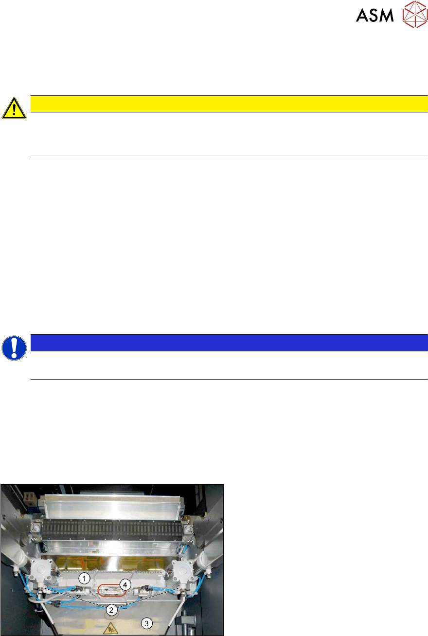
Fig.382: Connections
► Remove the four screws fastening the
waste tape slide(3)
and then remove
the waste tape slide.
► Unplug the compressed air connections
for the short-stroke cylinder (2)
at the
coupling.
► Unplug the electrical connections (4)
from the cutter(1). To do this, press the
sides of the connector.
9 Component feeding
9.1 Cutter
286 Service Manual SIPLACE X-Series S (from Hxxxx) 01/2021
WARNING
Risk of injury when releasing the fixtures!
The cutter is only held by the fastening screws and is not supported by other parts. If the
four fastening screws are loosened, the cutter will fall down and out of the machine.
► Make sure that no one is under the cutter.
► Support the cutter by placing a suitable object (e.g. height-adjustable support or chair)
under it.
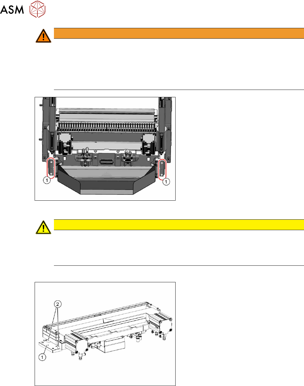
Fig.383: COT insert (example of SIPLACEX4S shown)
► Remove the four screws(1) fastening
the cutter holder.
If there are also washers or serrated
lock washers present, these will need
to be used again in the same places
during installation.
► Carefully lower the cutter and lift it out
of the machine.
CAUTION
Additional work
► For all further work, either fix the cutter to the mounting plate with four hexagon
socket-head screws M6 or use screw clamps to fasten the cutter to a sturdy table.
► Do not place the cutter onto the pneumatic connections down on the lifting cylinders.
Installation
Fig.384: Cutter (using example of X-Series)
► Remove the two holders(1) from both
sides of the cutter, together with the
distance sleeves(2)
.
There may be washers or serrated lock
washers present. Mark their positions,
to make clear assignment easier later
on.
9 Component feeding
9.1 Cutter
Service Manual SIPLACE X-Series S (from Hxxxx) 01/2021 287
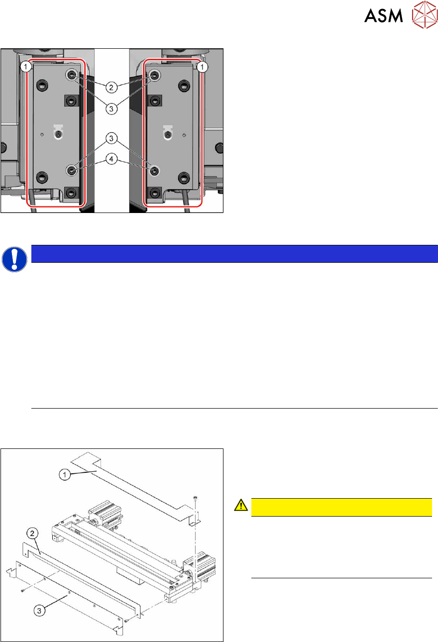
Fig.385: Fastening of new holder (example of
SIPLACEX4S shown)
1. 2x holder [03008869‑03]
2. 2x ISO4762-M4x16-A2-70
[03042507‑xx]
3. 4x serrated lock washers M4-
FST.1.4401 [03047857‑xx]
4. 2x ISO4762-M4x30-A2-70
[03042557‑xx]
To fit the holder, proceed as follows(1):
NOTICE
The spring rings used to date are no longer permissible. The mount must therefore
be changed.
► Only use the serrated lock washers [03047857‑xx] to fasten the rail [03008869‑03].
► Use the following screws to fasten the brackets:
2x ISO4762-M4x16-A2-70 [03042507-xx] and 2x ISO4762-M4x30-A2-70 [03042557-xx]
► If longer or shorter screws are used or if the serrated lock washers are missing, the
metal buffers will be subjected to excess strain and the screws could work loose. In
this case, the cutter fixtures are no longer reliable.
► Secure the screws with Loctite 243.
► Used screw clamps to protect the metal buffers from torsion during tightening.
► The maximum tightening torque is 2 Nm.
► Carefully lift the cutter onto the spacer sleeves. Use the spacer disks if provided.
► Tighten all four fastening screws.
Fig.386: Cutter (using example of X-Series)
1. Cover plate
2. Baffle plate
3. Protective plate
CAUTION!
There is a risk of injuring yourself on the
cutting edge of the blades.
For this reason, the deflector plate,
cover plate and protective sheet must
be left mounted!
.
► Move the cutter into its installation position, using the support/chair for assistance.
► Carefully lift the cutter into the planned position.
► Tighten all four fastening screws.
► Reconnect to the electrical and compressed air systems.
► Fit the waste tape container.
Follow the removal instructions in reverse order for further installation.