00198829-01_SM_X-Series-S_Hxxxx_EN.pdf - 第329页
9 Component feeding 9.2 COT insert Service Manual SIPLACE X-Series S (from Hxxxx) 01/2021 329 Fig.462: Sensor mount for 6x6 reject duct 1 Sensor 2 Metal sensor MK2 prefitted [03080138- xx] 3 ISO1479-ST3.5x6.5-C [0308021…
9 Component feeding
9.2 COT insert
328 Service Manual SIPLACE X-Series S (from Hxxxx) 01/2021
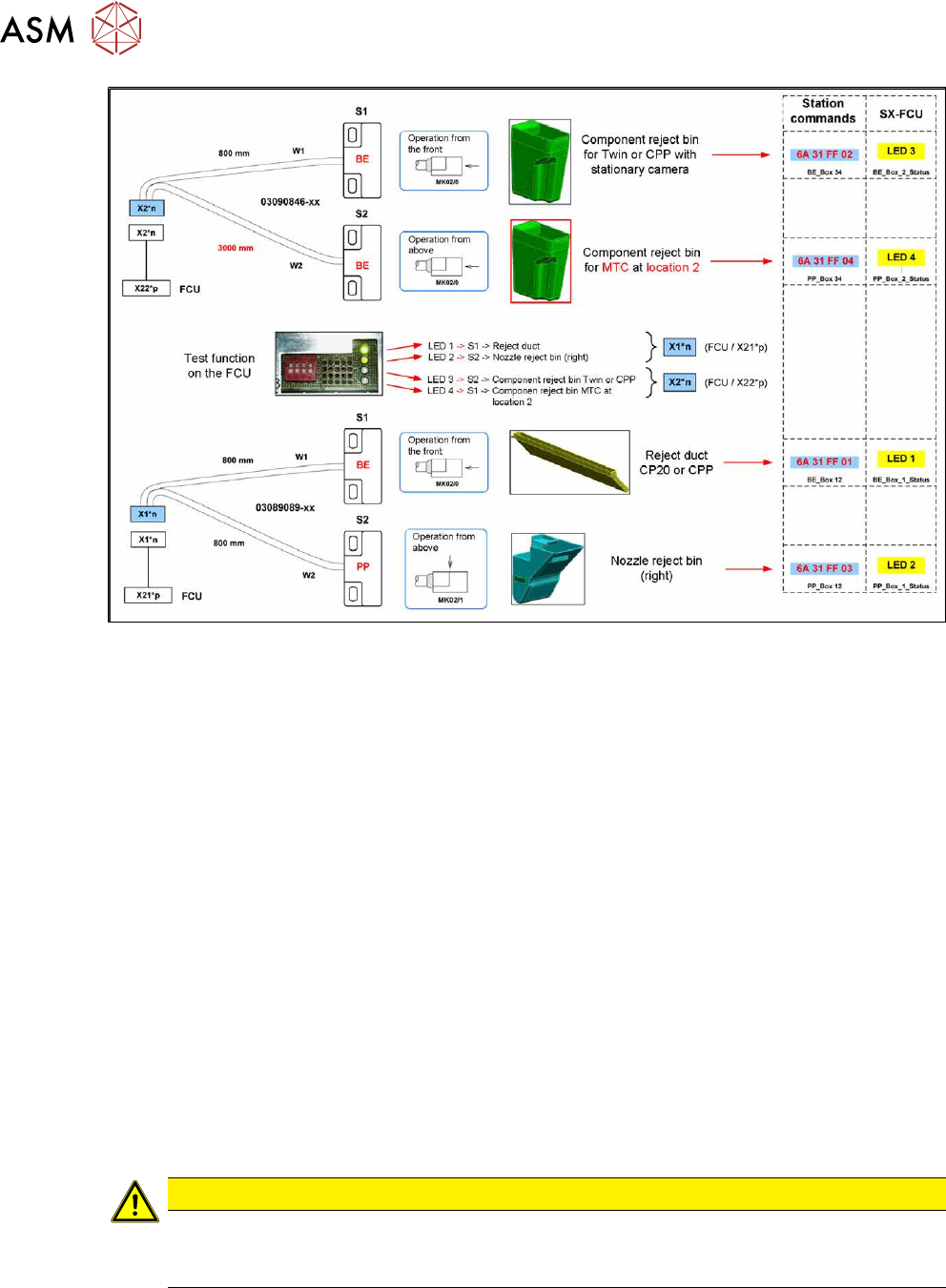
Fig.461: Overview: assignment of sensors (without JTF)
Removal
► Switch off the machine, disconnect it from the power supply and secure it to prevent
unauthorized reactivation.
1.2 "Preparatory work..." [}16]
► When replacing the reject bin sensors: remove the reject bin.
► When replacing the empty tape duct sensor: dismantle the nozzle changer.
2.8.3 "Replacing the Nozzle Changer" [}40]
► Disconnect the sensor.
► Dismantle the sensor.
Installation
Follow the removal instructions in reverse order for installation. Also observe the following instruc-
tions:
► Setting the sensor (see below).
Setting the reject bin 6x6 mm sensor for C&P 20 and CPP
Set the sensor so that this just triggers when the reject bin or reject duct is fitted.
The sensors react to magnetically conductive materials. For this reason, they may only be fixed
with plastic screws.
CAUTION
Danger of head crash
If the sensor is not set correctly, it may trigger too late. The reject bin could then protrude,
causing a head crash.
9 Component feeding
9.2 COT insert
Service Manual SIPLACE X-Series S (from Hxxxx) 01/2021 329
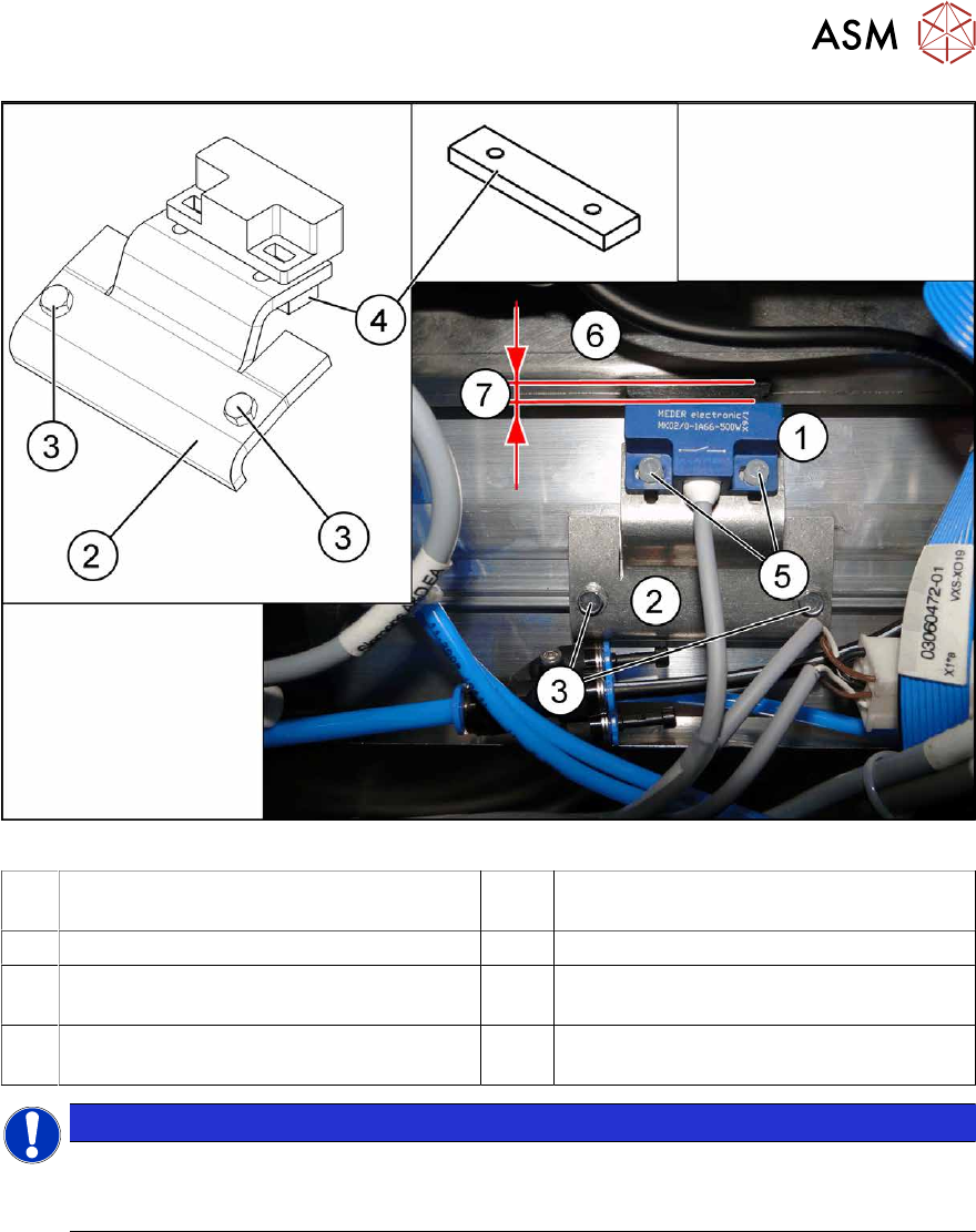
Fig.462: Sensor mount for 6x6 reject duct
1 Sensor 2 Metal sensor MK2 prefitted [03080138-
xx]
3 ISO1479-ST3.5x6.5-C [03080219-xx] 4 Bracket [03080137-xx]
5 PT screw 3.5x7-ST-10 galvanized
[03087342‑xx]
6 Component reject duct 6x6
7 The distance between the reject bin and
the sensor
NOTICE
Plastic screws
Only use the plastic screws provided to fasten the sensor (5) "PT screw 3.5x7-ST-10 gal-
vanized" [03087342‑xx]!
► Insert the reject bin 6x6.
► Use the slots to set the sensor with the bracket (4) and the plastic screws "PT screw 3.5x7-
ST-10 gal. zinc" [03087342‑xx] while the machine is running, so that it just reacts when the
reject bin is fitted (6)
. The distance (7) between the reject bin and the sensor must be 5 mm. If
the distance is less, the reject bin could then protrude, causing a head crash.
► Observe the display on the user interface while the machine is running or the LED status for
sensor S1 (right LED 1/left LED 3) in test mode on the FCU.
► The reject bin may not have more than 2 mm upwards play.
See also
2 2.8.2 "Reject bin and sensors - overview" [}38]
2 2.8 "Nozzle Changers and Reject Boxes" [}36]
9 Component feeding
9.3 X-Series Component Trolley
330 Service Manual SIPLACE X-Series S (from Hxxxx) 01/2021
9.3 X-Series Component Trolley
9.3.1 SIPLACE X-series component trolley
1
4
3
2
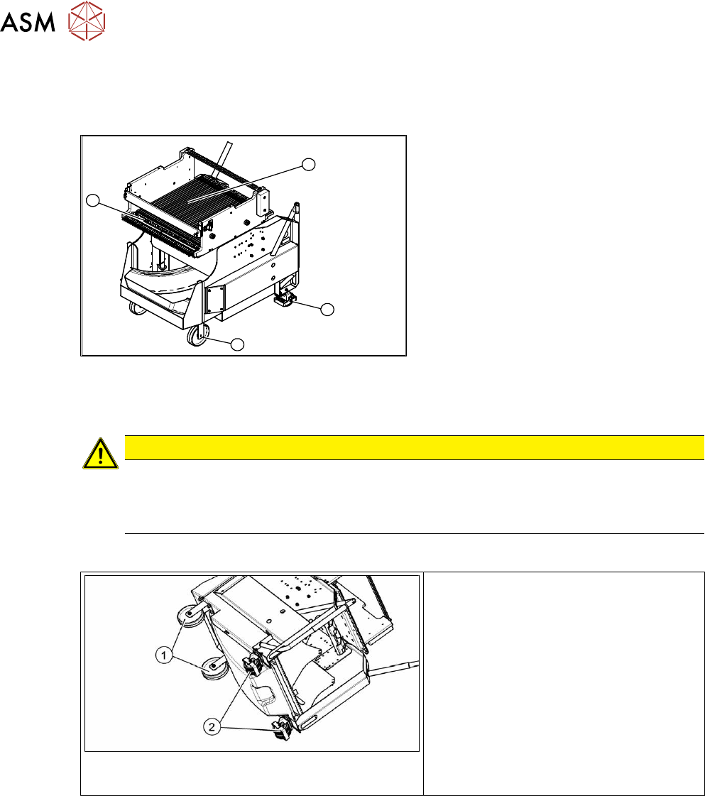
Fig.463: SIPLACE X-series component trolley
1. Guide castor
2. Fixed castor
3. Locking strip
4. Support block
9.3.2 Replacing the Fixed/Guide Castors [00341918-xx]
CAUTION
Heavy machine part!
The component trolley must be placed on one side in order to remove the fixed/guide
castors. The component changeover table is extremely heavy! You will need two people to
perform this task.
Parts, equipment and tools
Fig.464: Fixed and guide castors (example of SIPLACE
X‑Series shown)
1. Fixed castor [00341918-xx]
2. Guide castor [03004958-xx]
●
Second person
Removal/Installation
► Remove all feeders from the component trolley.
► Move the component trolley out of the machine.
► Place the component trolley down on its side, on a suitable surface.
► Remove the screws fastening the fixed/guide castor to be replaced and then remove the
castor.
► Insert the new fixed/guide castor.
► Stand the component trolley on its wheels again.