00198829-01_SM_X-Series-S_Hxxxx_EN.pdf - 第191页
7 Conveyor 7.5 Width Adjustment, Clamps and Cylinder Unit Service Manual SIPLACE X-Series S (from Hxxxx) 01/2021 191 7.5.10 Information About the Clamping Unit Versions (DC Only) NOTICE Old/new clamping unit A combinatio…
7 Conveyor
7.5 Width Adjustment, Clamps and Cylinder Unit
190 Service Manual SIPLACE X-Series S (from Hxxxx) 01/2021
7.5.9 Replacing the valve terminal for cylinders (width adjustment) (DC only)
Parts, equipment and tools
●
Valve terminal 3-fold [03092667-xx]
Overview
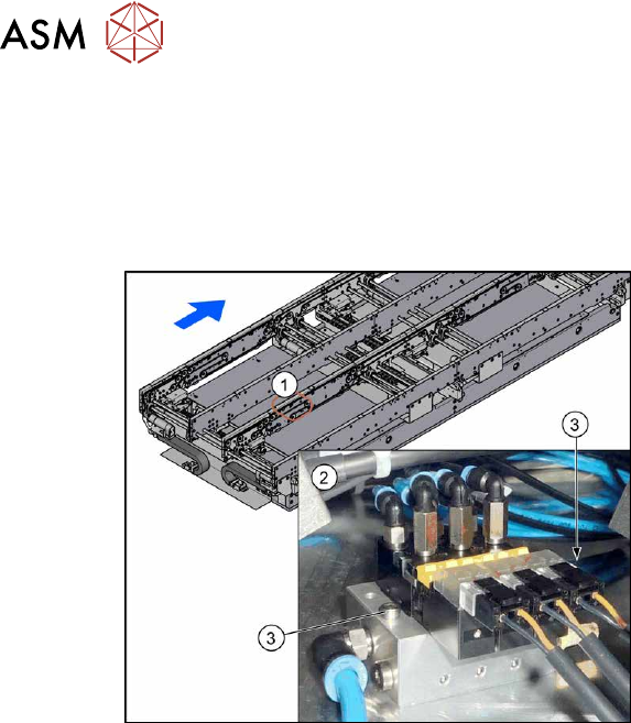
Fig.247: Overview of valve terminal
1. The valve terminal is located in the
center, between location 2 and 3, under
the lifting table plates.
2. Valve terminal
3. Fastening screws (2x) for valve ter-
minal
See also 7.5.1 "Overview of width adjustment" [}181]
Removal
► Use the software to move the conveyor sides into a position which allows you best access. As
an alternative, you can loosen the clamps for the relevant sides in dual conveyors.
7.2 "Loosening the Conveyor Side Clamps" [}162]
► Switch off the machine, disconnect it from the power supply and secure it to prevent
unauthorized reactivation.
1.2 "Preparatory work..." [}16]
► Switch off the compressed air supply
5.2 "Disabling the compressed air supply" [}86]
► Remove the screws fastening the lifting table plate at location 3 and remove the lifting table
plate.
7.3.1 "Replacing the lifting table plate" [}167]
► Remove the two screws fastening the valve terminal.
► Disconnect the valve terminal from the power and pneumatic connections. You might like to
mark their positions to make clear assignment easier later on.
► Take the valve terminal out of the machine.
Installation
Follow the removal instructions in reverse order for installation. Also observe the following instruc-
tions:
► Compare the old and the new valve terminal. You may sometimes have to refit the silencer
and pneumatic connections from the old valve terminal on the new valve terminal.
► Replace any opened cable ties.
7 Conveyor
7.5 Width Adjustment, Clamps and Cylinder Unit
Service Manual SIPLACE X-Series S (from Hxxxx) 01/2021 191
7.5.10 Information About the Clamping Unit Versions (DC Only)
NOTICE
Old/new clamping unit
A combination of old and new clamping units is possible.
Before installing a new clamping unit (version 2), make sure that your machine has
SW706.1 SP1 with Hotfix 4 or higher.
Overview
There are numerous versions of the clamping units. These differ, above all by the sensor flag:
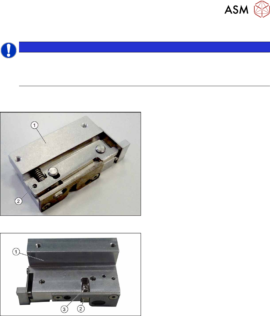
Fig.248: Clamp version 1
Version 1
1. Clamp
2. An M3x16 mm screw can be inserted
here to permanently release the clamp.
► For details about replacing the clamp-
ing units (version 1), read section Re-
placing the Clamping Unit (Version 1)
(DC Only).
Fig.249: Clamp version 2
Version 2
1. Clamp
2. Sensor switch
3. Fastening screw for sensor switch
► For details about replacing the clamp-
ing units (version 2), read section Re-
placing the Clamping Unit (Version 2)
(DC Only).
7 Conveyor
7.5 Width Adjustment, Clamps and Cylinder Unit
192 Service Manual SIPLACE X-Series S (from Hxxxx) 01/2021
7.5.11 Replacing the Clamping Unit (Version 1) (DC Only)
Parts, equipment and tools
Select the clamping unit needed:
NOTICE
New clamping units only
Clamping units with version 1 are being replaced with new downwards compatible version 2
clamping units. Spare parts are now only available for version 2 clamping units (see follow-
ing table).
Side (DC) Input area and center Output area
A Clamping unit A1 SXa [03092996Sxx] Clamping unit A2 SXa [03092973Sxx]
B Clamping unit B1 SXa [03092453Sxx] Clamping unit B2 SXa [03092891Sxx]
C Clamping unit C1 SXa [03092901Sxx] Clamping unit C2 SXa [03092712Sxx]
D Clamping unit D1 SXa [03092989Sxx] Clamping unit D2 SXa [03092997Sxx]
●
1 feeler gauge [00094020-xx]
●
1 feeler gauge 0.3mm
●
Torque wrench (2–25Nm) [00376625‑xx]
Overview
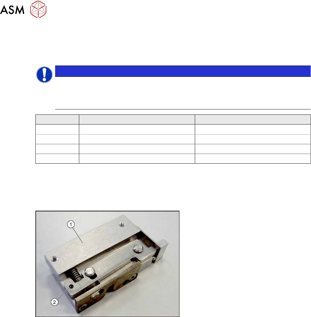
Fig.250: Clamp version 1
Version 1
1. Clamp
2. An M3x16 mm screw can be inserted
here to permanently release the clamp.
Version has no sensor flag.