00198829-01_SM_X-Series-S_Hxxxx_EN.pdf - 第140页
6 Gantries 6.5 MGCU 140 Service Manual SIPLACE X-Series S (from Hxxxx) 01/2021 6.5 MGCU 6.5.1 Replacing the MGCU Parts, equipment and tools ● Positioning control for the gantry axes MGCU-3 (3 axes) [03103477-xx] or ● Pos…

6 Gantries
6.4 Trailing cable and printed circuit boards
Service Manual SIPLACE X-Series S (from Hxxxx) 01/2021 139
Troubleshooting
Error:
●
Image transmission errors occur at cameras of type GigE.
●
Potential error message:
FM 33332: image transmission to SIPLACE Vision computer interrupted.
Solution
●
Check the DIP switches for the VHI. Pay attention to the function state of
the board.
Error:
●
When starting the station software, cameras of type GigE are sometimes
not recognized.
●
Potential error messages:
FM 33378: unable to address camera (242).
FM 33209: unable to initialize camera with specified sensor ID.
FM 31904: unable to initialize machine hardware.
Solution
●
Contact the SIPLACE Service team for details.
Error:
●
This would lead to communication errors with one or more cameras.
●
There are communication errors with one or more cameras.
Solution
●
Please contact the SIPLACE service team for more information.
Give them the following reference number: TI2019-11V01.
6 Gantries
6.5 MGCU
140 Service Manual SIPLACE X-Series S (from Hxxxx) 01/2021
6.5 MGCU
6.5.1 Replacing the MGCU
Parts, equipment and tools
●
Positioning control for the gantry axes MGCU-3 (3 axes) [03103477-xx]
or
●
Positioning control for the gantry axes MGCU-2 (2 axes) [03117531-xx]
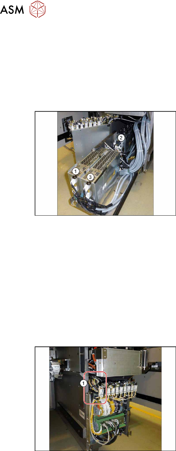
Overview
Fig.179: Overview of MGCUs
(1) to (3) MGCUs
The MGCUs are located in a rack unit
between locations 1 and 2.
MGCU 2 is fitted with the fans above and
MGCU 1 and 3 are fitted with the fans
below.
The MGCU type and the assignment of MGCUs to gantries differs according to the machine type.
6.5.3 "Overview of MGCUs" [}143]
Removal
► Switch off the machine, disconnect it from the power supply and secure it to prevent
unauthorized reactivation.
1.2 "Preparatory work..." [}16]
► Unplug all connections from the MGCU. If necessary, mark their positions to make clear as-
signment easier later on.
► Remove the screws fastening the mount and then remove the mount.
► Remove the MGCU from the machine.
Installation
Follow the removal instructions in reverse order for installation. Also observe the following instructions:
Fig.180: Cable
► Use the DIP switch to set the gantry ID
on the MGCU (see 6.5.3
"Overview of
MGCUs" [}143]).
► Always make sure that the cables do
not rub against any parts or are folded.
Pay particular attention to the
cables(1)
at the top end of the flap.
► Check the firmware and perform a
download, if needed. (see 10.1
"eSW
Download (SW 70x)" [}379]).
6 Gantries
6.5 MGCU
Service Manual SIPLACE X-Series S (from Hxxxx) 01/2021 141
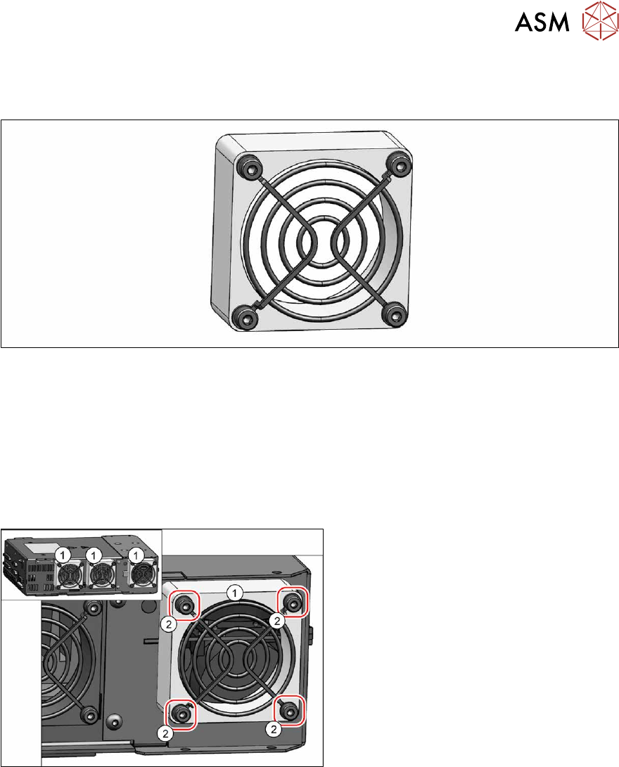
6.5.2 Replacing the MGCU fan
Parts, equipment and tools
Fig.181: Cooling fan
●
Fan [03104136‑xx]
Removal
► Switch off the machine, disconnect it from the power supply and secure it to prevent
unauthorized reactivation.
1.2 "Preparatory work..." [}16]
► Remove the MGCU.
6.5.1 "Replacing the MGCU" [}140]
Fig.182: Cooling fan
► Unplug the cable from the fan (1). You
may want to mark the position, to make
clear assignment easier later on.
► Remove the four screws (2) (M4x30)
fastening the fan and then remove the
fan.