00198829-01_SM_X-Series-S_Hxxxx_EN.pdf - 第146页
6 Gantries 6.6 MHCU, boards and camera 146 Service Manual SIPLACE X-Series S (from Hxxxx) 01/2021 6.6 MHCU, boards and camera 6.6.1 Replacing the MHCU, basic and head adapter Parts, equipment and tools The following spar…
6 Gantries
6.5 MGCU
Service Manual SIPLACE X-Series S (from Hxxxx) 01/2021 145
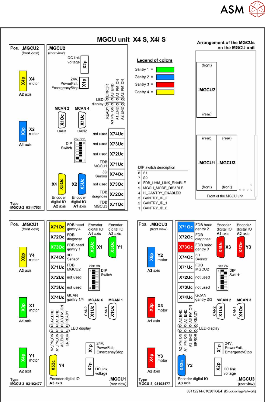
Fig.186: Overview of MGCUs on X4 S and X4i S
6 Gantries
6.6 MHCU, boards and camera
146 Service Manual SIPLACE X-Series S (from Hxxxx) 01/2021
6.6 MHCU, boards and camera
6.6.1 Replacing the MHCU, basic and head adapter
Parts, equipment and tools
The following spare parts can be replaced:
●
MHCU assembly, compatible [03090990Sxx] from FS04
●
PCB / X base adapter C&P [03045647Sxx] from FS08
●
Module / X base adapter TWIN [03062201Sxx]
Head Adapter Number of MHCU, base adapters
CP20A
CPP
Module X base adapter C&P
[03071420-xx]
1x MHCU [03090990Sxx] from FS04
1x PCB / X base adapter C&P
[03045647Sxx] from FS08 *
CP20P Module X base adapter CP20P
[03109399-xx]
1x MHCU [03090990Sxx] from FS04
1x PCB / X base adapter C&P
[03045647Sxx] from FS08 *
Twin Head adapter Twin HCU / SX4
[03082096-xx]
2x MHCU [03090990Sxx] from FS04
1x module/ X base adapter TWIN
[03062201Sxx]
* You need a PCB/X base adapter C&P [03045647Sxx] with FS08 or higher. From FS08 onwards,
longer flat ribbon cables are needed. These are provided in [03045647Sxx].
Removal
► Switch off the machine, disconnect it from the power supply and secure it to prevent
unauthorized reactivation.
1.2 "Preparatory work..." [}16]
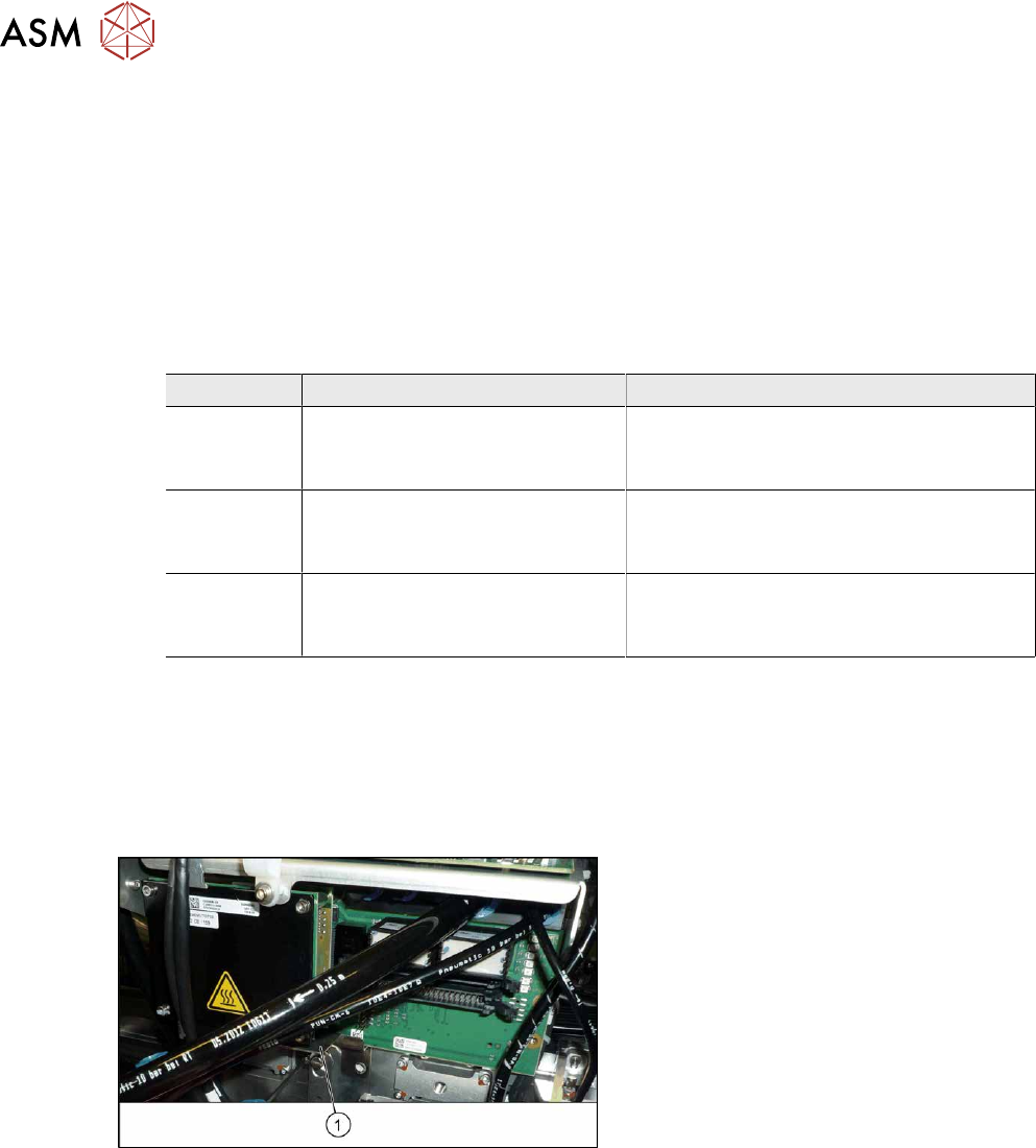
Fig.187: Protective plate
► You may need to dismantle the place-
ment head for better access. Read the
relevant chapter, section Placement
heads, if required.
► Remove the two screws fastening the
protective plate(1)
(if present) and
remove the protective plate.
6 Gantries
6.6 MHCU, boards and camera
Service Manual SIPLACE X-Series S (from Hxxxx) 01/2021 147
Fig.188: Head adapter MHCU
► Unplug all electrical connections to the
head adapter(1)
. You may want to
mark the positions of these connections
to make clear assignment easier later
on.
NOTICE!
SIPLACE X-Series S
You may need to also disconnect the
compressed air sensor on SIPLACE
C&P20P/P2 heads.
.
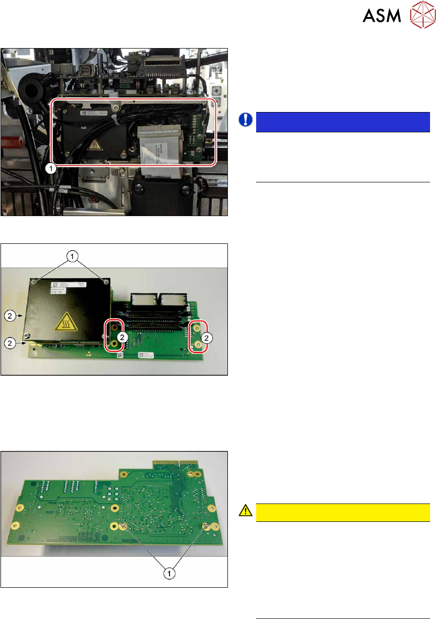
Fig.189: MHCU
► Remove all the screws(2) fastening the
board.
► In addition, the board is fastened with
the topmost two MHCU screws(1)
in
each case. Remove these screws as
well.
► Carefully pull the board down and off.
Make sure that the head adapter board
is connected to the head interface via a
press-fit connection and two other
screws from below.
Converting the MHCU
If you have ordered the base adapter without new MHCU(s), you will have to convert the MHCU(s)
from the old to the new basic adapter. To do so, proceed as follows:
Fig.190: Fastening screws on the back
► Remove the two screws(1) fastening
the MHCU on the back of the board
and carefully pull the MHCU off the
base adapter.
CAUTION!
Washers and pins
Make sure that you do not lose the
washers. Make a note of the number
of washers used for each screw, as
this may well differ. These will need to
be fitted back in again as well.
Make sure that you do not damage the
pins under the MHCU.
.
► Repeat the procedure, if needed, for the second MHCU (for Twin only).
Installation
Follow the removal instructions in reverse order for installation. Also observe the following instruc-
tions:
► Checking the embedded software and performing a download if needed (see LINK).
10.1 "eSW Download (SW 70x)" [}379]