00198829-01_SM_X-Series-S_Hxxxx_EN.pdf - 第164页
7 Conveyor 7.2 Loosening the Conveyor Side Clamps 164 Service Manual SIPLACE X-Series S (from Hxxxx) 01/2021 Fig.212: Width adjustment belt (example of SIPLACE X4S with dual conveyor shown) ► Carefully pull on the widt…
7 Conveyor
7.2 Loosening the Conveyor Side Clamps
Service Manual SIPLACE X-Series S (from Hxxxx) 01/2021 163
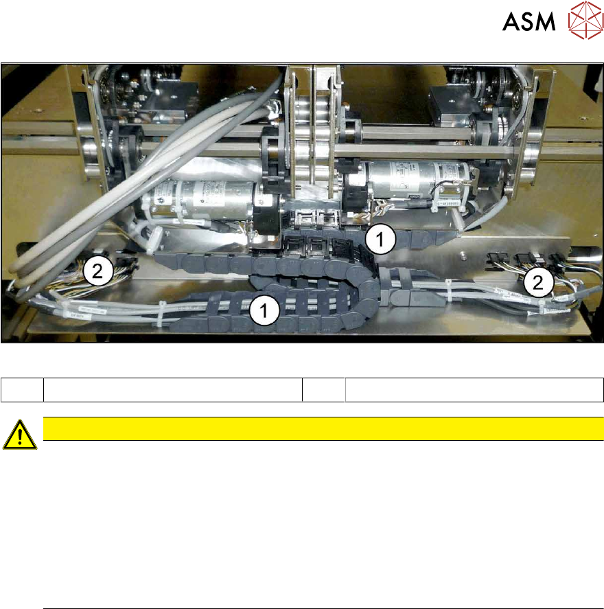
Fig.211: Trailing cable and interface connector
1 Trailing cable 2 Interface connector
CAUTION
Outer conveyor sides can only be moved to center
If the outer conveyor sides are manually moved, the trailing cable could collide with the interface
connectors underneath the conveyor sides. To avoid this, observe the following points:
► The conveyor sides A, B and C may only be moved as far as the "stopper right side D"
on the outermost left edge of the lifting table plate of conveyor lane 1.
► The conveyor sides D, C and B may only be moved as far as the "stopper left side A"
on the outermost right edge of the lifting table plate of conveyor lane 2.
ð If the conveyor sides are moved using the software, this will automatically be taken
into account.
7.2.1 Manually Moving the Conveyor Sides with the Help of the Adjustment Units
Docking in the adjustment units
If you are unable to move the sides with the software (e.g. due to a sensor error), proceed as follows:
► Switch off the machine, disconnect it from the power supply and secure it to prevent
unauthorized reactivation.
1.2 "Preparatory work..." [}16]
► Switch off the BoxPC.
► Dismantle the lifting table plate at location 3.
► Switch the machine on (without BoxPC). The machine is now supplied with compressed air.
7 Conveyor
7.2 Loosening the Conveyor Side Clamps
164 Service Manual SIPLACE X-Series S (from Hxxxx) 01/2021
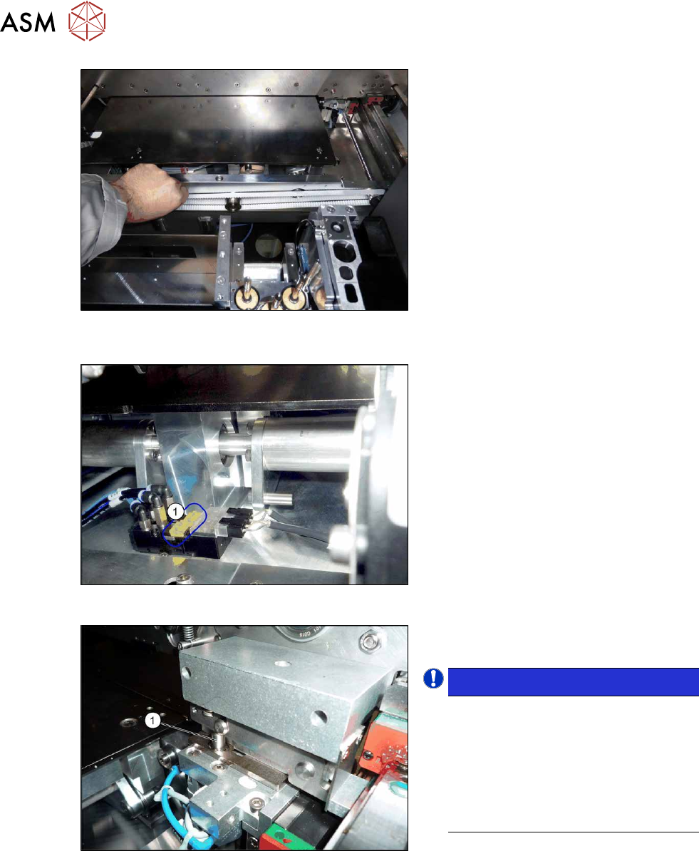
Fig.212: Width adjustment belt (example of SIPLACE X4S
with dual conveyor shown)
► Carefully pull on the width adjustment
belt to move the adjustment units until
they are under the clamps and the
short-stroke cylinder can activate the
clamps.
Fig.213: Solenoid valves (example of SIPLACE SX1 shown)
► Operate the solenoid valves (individu-
ally if needed) using the yellow slide
switches(1)
. This moves the cylinders
out, which then loosen the clamps.
Fig.214: Cylinder engaged
► Make sure that all side cylinders(1)
have engaged.
NOTICE!
The adjustment units need to be posi-
tioned under the conveyor side so that
all engage at the same time. If this is
not possible, check the parallelism of
the adjustment units. If these are OK,
the conveyor side may be distorted. In
this case, call the SIPLACE Service
team.
.
► Carefully pull on the width adjustment belt to move the conveyor side.
► Repeat these steps if needed for any other conveyor sides.
7 Conveyor
7.2 Loosening the Conveyor Side Clamps
Service Manual SIPLACE X-Series S (from Hxxxx) 01/2021 165
7.2.2 Moving the Conveyor Sides by Manually Releasing the Side Clamps
Parts, equipment and tools
●
Per side:
3x ISO4762-M3x16-A2-70 [03042545-xx]
Procedure
► Move the conveyor sides to a position which gives you good access to the clamps.
► Switch off the machine, disconnect it from the power supply and secure it to prevent
unauthorized reactivation.
1.2 "Preparatory work..." [}16]
NOTICE
Marking the starting positions
After completing this task, it is helpful to move the conveyor sides back to their approximate
starting positions.
► You may want to mark the current positions of the conveyor sides.
Do not mark the clamping surface or the guide rails.
CAUTION
Loosen all clamps
You always need to loosen all clamps for one conveyor side.
Version 1
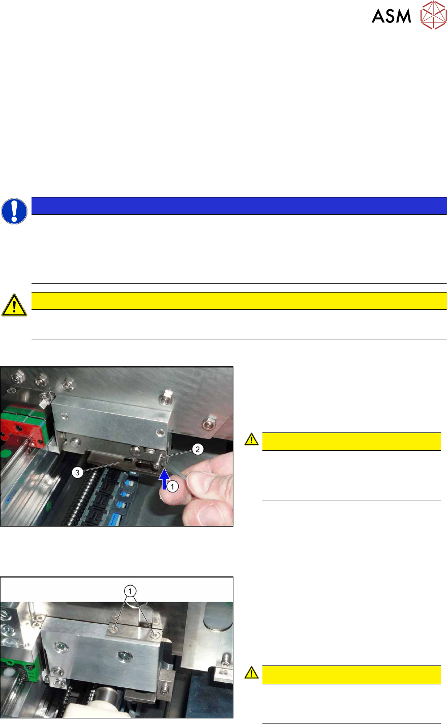
Fig.215: Clamp
► Loosen the conveyor side clamps.
To do this, press the clamp(1)
(e.g.
with a screwdriver) upwards and turn or
insert a screw (M3x16) into the
hole(2)
.
CAUTION!
Make sure that you do not distort the
guide plate(3)
. If you do, this could
lead to problems with recognizing the
position of the conveyor side.
.
Version 2
Fig.216: Clamp
► Loosen the clamps on the conveyor
sides.
To do this, remove the disks above the
clamp compression springs (2 screws
for each disk). To do this, undo both
screws (1)
on the clamps (2x for each
conveyor side).
CAUTION!
Compression springs
The compression springs are tensioned.
Make sure that you do not lose these.
.