00198829-01_SM_X-Series-S_Hxxxx_EN.pdf - 第327页
9 Component feeding 9.2 COT insert Service Manual SIPLACE X-Series S (from Hxxxx) 01/2021 327 9.2.12 Replacing the Reject Bin Sensors Parts, equipment and tools ● Reject bin query X-Series S [03089087-xx] Overview Fig.4…
9 Component feeding
9.2 COT insert
326 Service Manual SIPLACE X-Series S (from Hxxxx) 01/2021
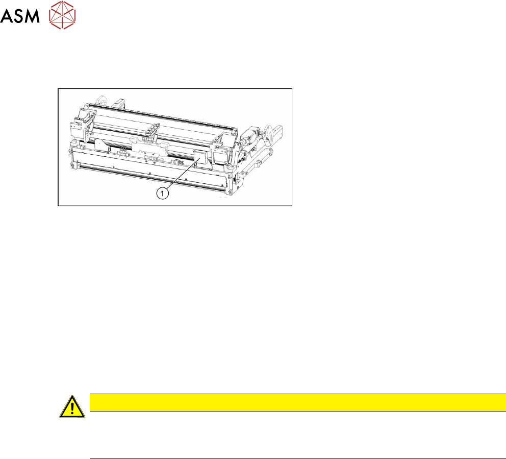
9.2.11 Replacing the infeed control
Parts, equipment and tools
Fig.457: Feed control
1. Infeed control assembly SX4
[03082077-xx]
Removal
► Switch off the machine, disconnect it from the power supply and secure it to prevent
unauthorized reactivation.
1.2 "Preparatory work..." [}16]
► Dismantle the nozzle changer over the feed control.
2.8.3 "Replacing the Nozzle Changer" [}40]
► To gain better access, you may need to disconnect the COT insert and pull it slightly out of
the machine. Observe the instructions in section 9.2.2
"Installation Positions of COT Insert and
Manual Table (Table Positions)" [}313].
You can improve access by removing the upper section of the stationary camera, if present.
2.7 "Stationary component camera" [}33]
CAUTION
Component camera
► The component camera mirror has sharp edges.
► Take care not to damage the component camera.
► Unplug all electrical connections to the insert control. You may want to mark the positions of
these connections to make clear assignment easier later on.
► Remove the screws fastening the infeed control and remove the insert control from the
machine.
Installation
Follow the removal instructions in reverse order for installation.
9 Component feeding
9.2 COT insert
Service Manual SIPLACE X-Series S (from Hxxxx) 01/2021 327
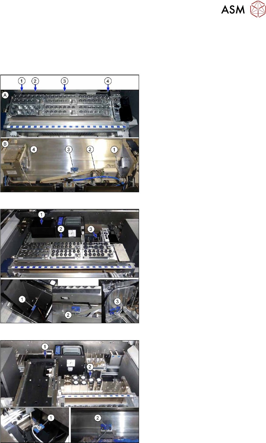
9.2.12 Replacing the Reject Bin Sensors
Parts, equipment and tools
●
Reject bin query X-Series S [03089087-xx]
Overview
Fig.458: Sensors on standard COT insert
A) View from above
B) View from back
1. Connector for additional sensors
2. Connector for sensors (3) and (4)
3. Sensor for reject channel C&P20P
4. Sensor for reject bin (nozzles and com-
ponents CPP)
Fig.459: Sensors on COT insert with SPS
1. Sensor component reject bin (Twin and
CPP with stationary camera)
2. Sensor for reject channel C&P20 P
3. Sensor for reject bin (nozzles and com-
ponents CPP)
Fig.460: Sensors on COT insert with JTF
1. 2x sensors
Reject bin (Twin Head and CPP with
stationary camera)
Reject bin (nozzles)
2. Sensor for reject channel C&P20 P
9 Component feeding
9.2 COT insert
328 Service Manual SIPLACE X-Series S (from Hxxxx) 01/2021
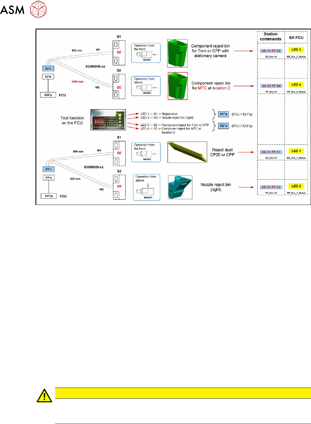
Fig.461: Overview: assignment of sensors (without JTF)
Removal
► Switch off the machine, disconnect it from the power supply and secure it to prevent
unauthorized reactivation.
1.2 "Preparatory work..." [}16]
► When replacing the reject bin sensors: remove the reject bin.
► When replacing the empty tape duct sensor: dismantle the nozzle changer.
2.8.3 "Replacing the Nozzle Changer" [}40]
► Disconnect the sensor.
► Dismantle the sensor.
Installation
Follow the removal instructions in reverse order for installation. Also observe the following instruc-
tions:
► Setting the sensor (see below).
Setting the reject bin 6x6 mm sensor for C&P 20 and CPP
Set the sensor so that this just triggers when the reject bin or reject duct is fitted.
The sensors react to magnetically conductive materials. For this reason, they may only be fixed
with plastic screws.
CAUTION
Danger of head crash
If the sensor is not set correctly, it may trigger too late. The reject bin could then protrude,
causing a head crash.