00198829-01_SM_X-Series-S_Hxxxx_EN.pdf - 第221页
7 Conveyor 7.8 Laser light barriers, fiber optic cable and PCB sensors Service Manual SIPLACE X-Series S (from Hxxxx) 01/2021 221 ► Remove the transmitter/receiver. 7.8.1 "Replacing the Laser Light Barrier for the T…
7 Conveyor
7.8 Laser light barriers, fiber optic cable and PCB sensors
220 Service Manual SIPLACE X-Series S (from Hxxxx) 01/2021
Other cables
Part to be replaced Correct spare part
[03092517‑xx] Cable W49 side panel D1 sensor LLB1 L=1360 mm Cable PCB centering
receiver LLB2
L=1850 mm
[03088522‑xx]
[03092518‑xx] Cable W50 side panel D1 sensor LLB2 L=1020 mm
[03093772‑xx] Cable W69 side panel D2 sensor LLB1 L=950 mm
[03093773‑xx] Cable W70 side panel D2 sensor LLB2 L=1420 mm
[03088490‑xx] Cable W21 side panel A1 laser LLB1, LLB2 L=940 mm Cable PCB centering
LLS1, LLS2, L=1860
mm [03088856‑xx]
[03088493‑xx] Cable W43 side panel A2 laser LLB1, LLB2 L=1360 mm
NOTICE
Labeling the cable
► Label the new cable identically to the cable which is to be replaced. If the cable is too
long, stow the excess length in the conveyor base, near the connection. Fix the cables
with a cable tie, where necessary.
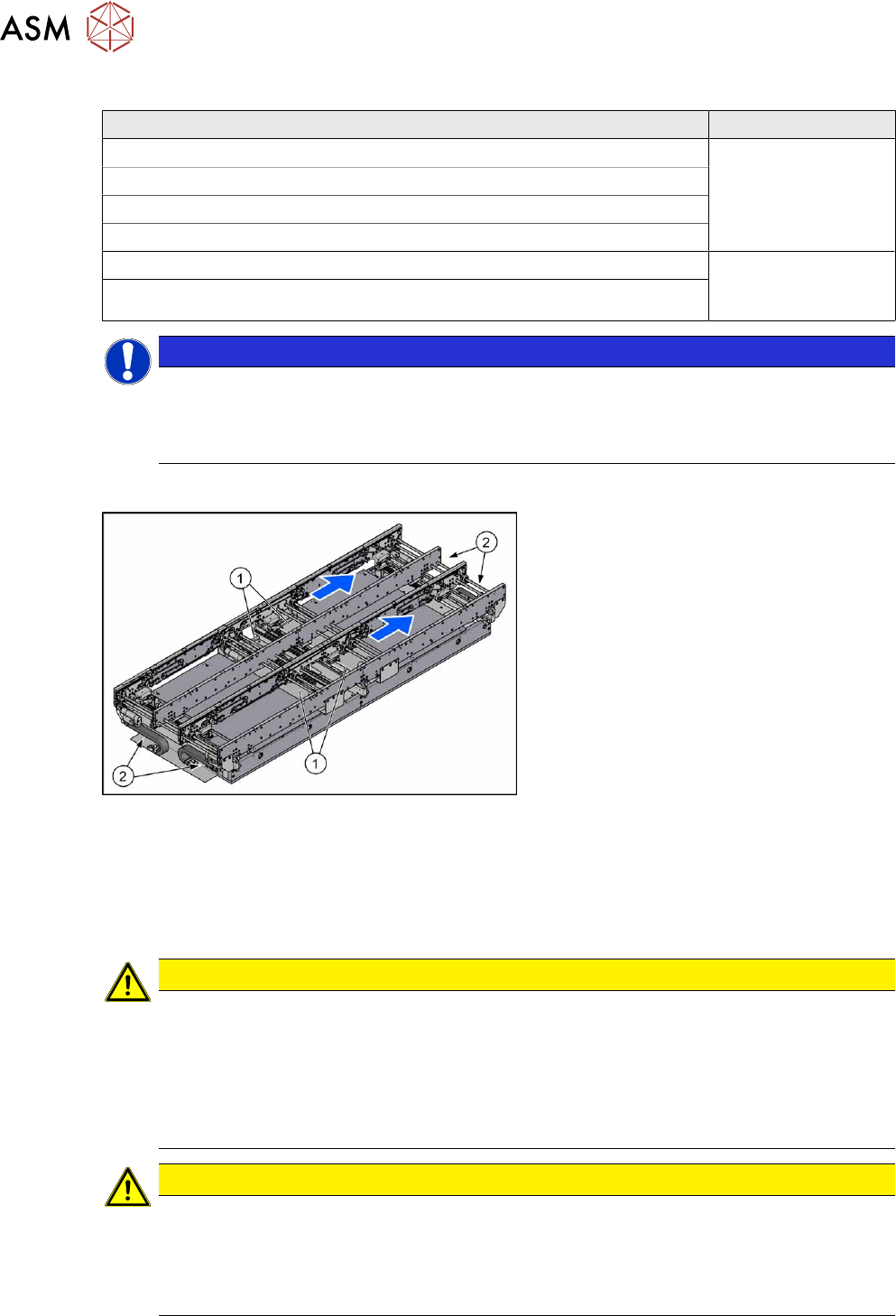
Overview
Fig.287: Overview of conveyor controls
The cables for the laser light barriers are
either connected directly to the conveyor
controls(1)
or to the input or output area(2)
of the conveyor.
For details of the conveyor control, see
7.9.1.1
"Conveyor control TSP420" [}242].
Removal
► Switch off the machine, disconnect it from the power supply and secure it to prevent
unauthorized reactivation.
1.2 "Preparatory work..." [}16]
CAUTION
Move the conveyor sides carefully!
The clamping and guide rails are a key stabilizing element for the conveyor side, which is
then less stable once they have been removed.
► Move the opened conveyor sides very carefully.
► Make sure that the sides are always pushed equally on the left and right.
► Make sure that you do not distort the sides.
CAUTION
Make a note of the order in which the cables are run!
The room in the side walls is limited. Therefore, make sure that no cables are crossed over,
particularly in the output area, from the trailing cable to the laser light barrier.
Make a note of the order in which the cables are run in the side panel, so that you can run
them neatly and correctly again later on.
7 Conveyor
7.8 Laser light barriers, fiber optic cable and PCB sensors
Service Manual SIPLACE X-Series S (from Hxxxx) 01/2021 221
► Remove the transmitter/receiver.
7.8.1 "Replacing the Laser Light Barrier for the Transmitter/Receiver" [}216]
► You might need to dismantle other guide rails in order to thread the cable out of the conveyor
side, as far as the trailing cable.
7.7.3 "Replacing the Clamping Rail/Belt Guidance" [}210]
► You might want to move hexagonal shafts in order to create more room for movement.
7.6.6 "Replacing the hexagonal shaft" [}205]
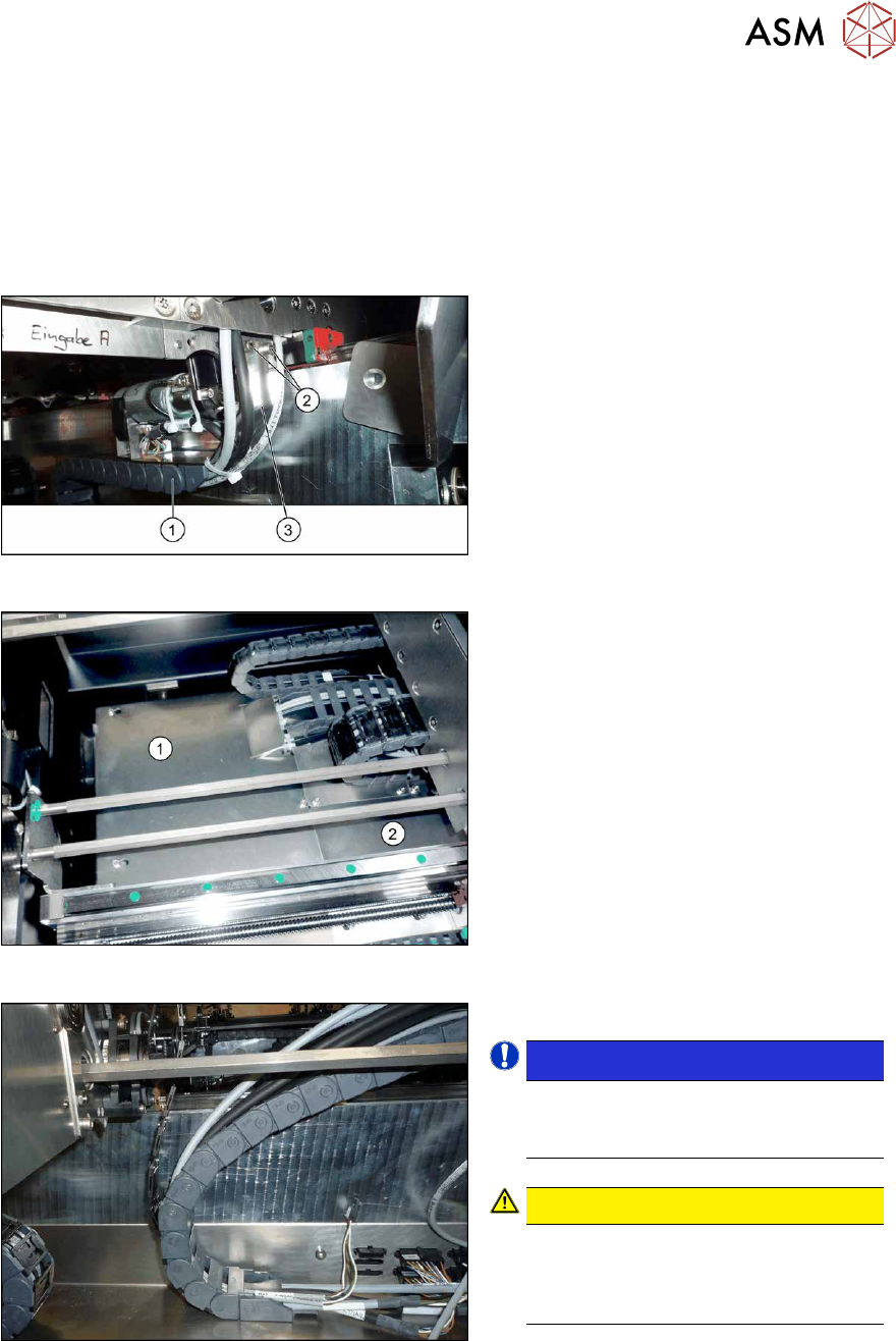
Fig.288: Holding plate
► Remove the screws(2) fastening the
bracket(3)
to the top end of the trailing
cable(1)
on the conveyor side.
► For better access, you can remove the
screws fastening the trailing cable to
the bracket.
Fig.289: Cover plates (example of SX1/SX2 shown)
► In the intermediate conveyor: dismantle
the two cover plates(1)
and (2) under
the trailing cable. To do this, loosen the
four fastening screws for each and then
remove the cover plates.
Fig.290: Opened trailing cable
► Open the trailing cable.
NOTICE!
There is also a protective tape in the
trailing cable. This separates the fiber
optic cable from the cables.
.
CAUTION!
Make sure you do not bend the fiber
optic cable. These could otherwise be-
come cloudy or break and no longer
transmit the signal properly.
.
► For better access, you can remove the
screws fastening the trailing cable to
the bottom of the conveyor.
► Thread the cable out of the conveyor
side and the trailing cable.
7 Conveyor
7.8 Laser light barriers, fiber optic cable and PCB sensors
222 Service Manual SIPLACE X-Series S (from Hxxxx) 01/2021
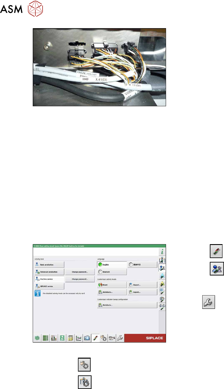
Fig.291: Connections (here output conveyor location 3)
► Disconnect the cable. You may want to
mark the position, to make clear as-
signment easier later on.
Installation
Follow the removal instructions in reverse order for installation. Also observe the following instruc-
tions:
► Leave enough room at the cable for easy removal of the transmitter/receiver from the side
wall. Make sure that the connector is not directly under the housing, otherwise you might have
problems inserting the module.
► Replace any open cable ties.
Make sure that the cable ties and the heads of the cable ties do not rub against any parts
when you do this.
► Check the setting for the transmitter/receiver and correct if necessary.
► Teach the PCB sensors.
7.8.3 Checking the laser light barrier
Whenever the laser light barrier is dismantled, it then needs to be checked and manually set again,
if necessary. Check the setting as follows:
Fig.292: Select operator level
► Select the button.
► Select the button.
► Switch over to the operator level Ma-
chine service.
ð The button will be shown.
► Click on the button, to switch over to the menu Check sensors and functions.
► Click on the button.