00198829-01_SM_X-Series-S_Hxxxx_EN.pdf - 第32页
2 Basic Machine 2.6 Replacing the machine foot 32 Service Manual SIPLACE X-Series S (from Hxxxx) 01/2021 2.6 Replacing the machine foot DANGER Heavy machine part ► The machine feet are very heavy. When screws are loosene…
2 Basic Machine
2.5 Replacing the barcode laminate for the X feeder
Service Manual SIPLACE X-Series S (from Hxxxx) 01/2021 31
2.5 Replacing the barcode laminate for the X feeder
Parts, equipment and tools
Select a suitable barcode laminate:
●
1D barcodes:
– Barcode laminate X feeder sector 1 SX4 [03085971-xx]
– Barcode laminate X feeder sector 2 SX4 [03085976-xx]
– Barcode laminate X feeder sector 3 SX4 [03085994-xx]
– Barcode laminate X feeder sector 4 SX4 [03085995-xx]
●
2D barcodes:
– Barcode set for 4 locations [03216618‑xx]
NOTICE!
Always replace all
If using barcode laminates with 2D barcodes, all four bar-
code laminates and all four MID labels must be replaced.
It is not possible to replace individual barcode laminates
as the MID is in the 2D barcode and this is unique.
.
You also need the following:
●
Cleaning agent
CAUTION
ESD coating
The choice of cleaning agent for the protective covers must be made with particular care so
as not to damage the ESD coating on the protective covers! Never use acid or strong al-
kaline agents and avoid all ketones, esters, aromatics, halogenated hydrocarbons, essen-
tial oils or similar.
► Only apply light pressure as you clean the protective covers so as not to damage the
ESD coating!
Removal
► Remove the old barcode laminate.
Installation
Follow the removal instructions in reverse order for installation. Also observe the following instructions:
► Make sure that the adhesive surface is clean and free of grease. Clean if necessary.
► Make sure that the tracks shown on the label match those of the table or the track label.
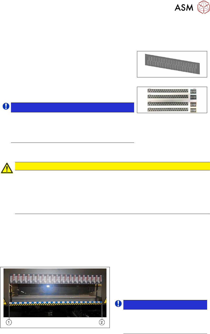
Fig.19: Positioning the barcode ruler
► The barcode ruler must be flat against
the disk on the left of all locations (1)
.
► The track ruler must always be placed
so that it indicates towards the machine
center(2)
.
NOTICE!
Recommendation
Place the two 8mm feeders on
tracks1 and40, in order to estimate
the correct position more precisely.
.
2 Basic Machine
2.6 Replacing the machine foot
32 Service Manual SIPLACE X-Series S (from Hxxxx) 01/2021
2.6 Replacing the machine foot
DANGER
Heavy machine part
► The machine feet are very heavy. When screws are loosened, there is a risk that
these could fall down and crush limbs.
► When replacing the machine feet, you need to raise the machine approx. 50 cm.
► Make sure that there is nobody in the hazard area. The unintentional movement or
lowering of the machine can create a risk of crushing limbs.
CAUTION
Do not move the machine
► Make sure that the machine is not moved and that the conveyor sides are not dam-
aged.
Parts, equipment and tools
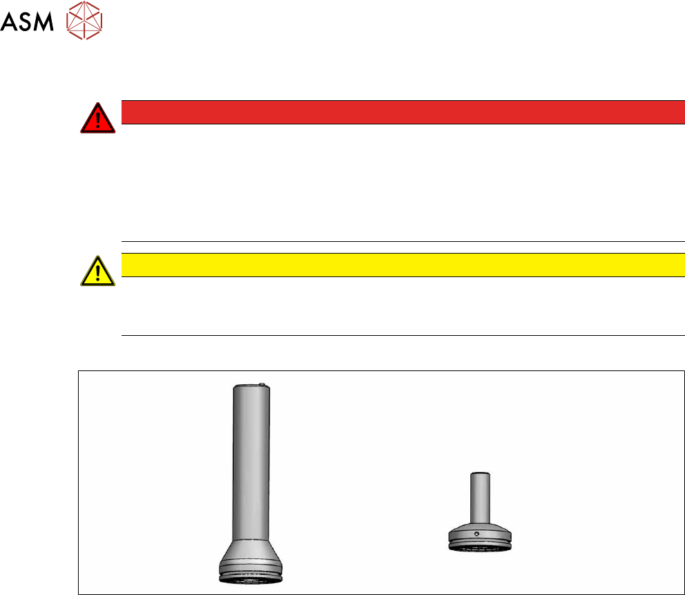
Fig.20: Machine foot [03000890-xx] and machine foot HF [03002561-xx]
●
Machine foot [03000890-xx] or
Machine foot HF [03002561-xx]
●
Instruction manual for your machine
Removal/installation
► Please read the relevant chapter of the instruction manual:
– "Presetting the height of the middle machine feet"
– "Presetting the height of the outer machine feet"
2 Basic Machine
2.7 Stationary component camera
Service Manual SIPLACE X-Series S (from Hxxxx) 01/2021 33
2.7 Stationary component camera
2.7.1 Replacing the stationary component camera
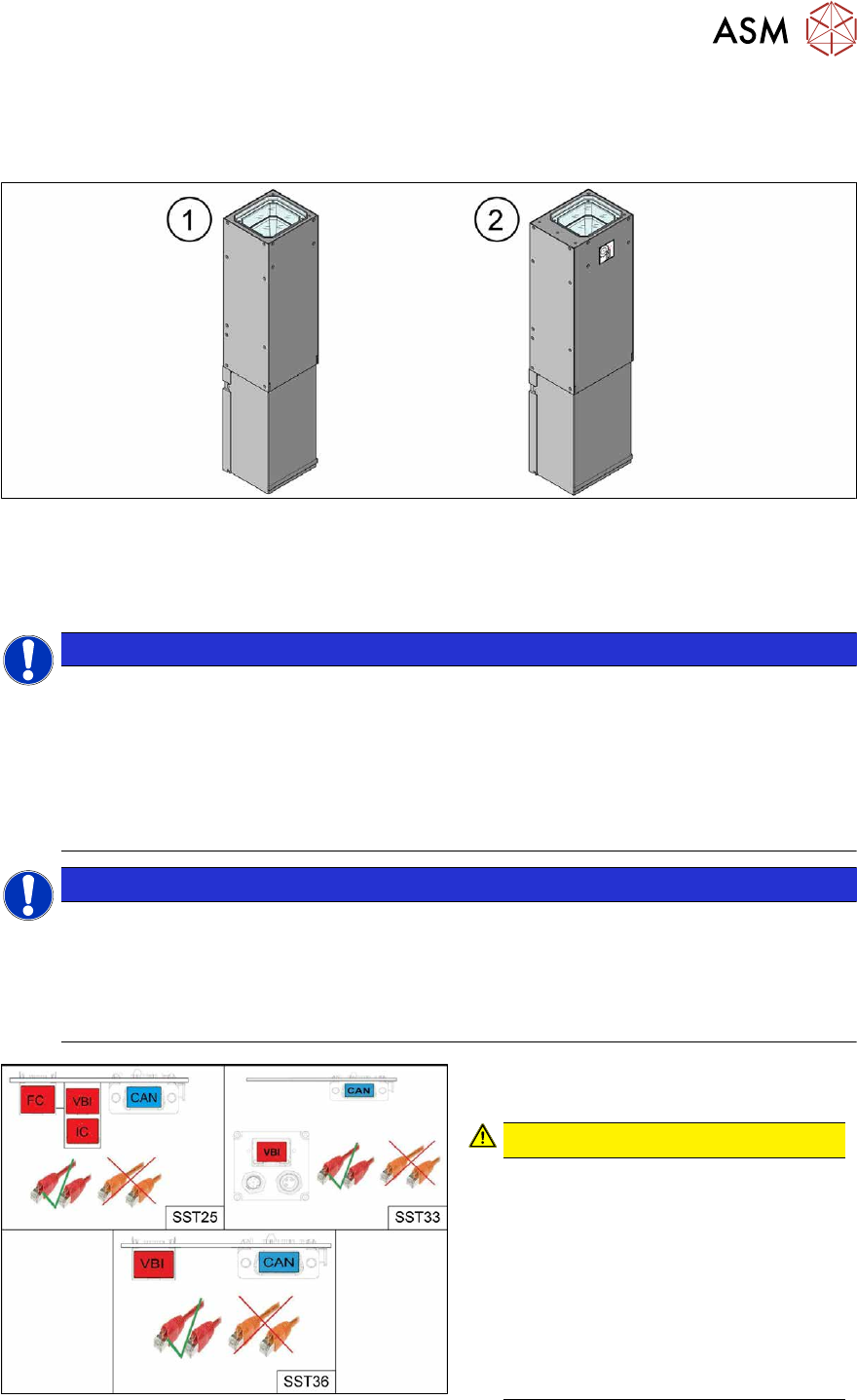
Fig.21: Stationary cameras SST25(1) and SST33(2)
Read the assembly instructions for this:
●
Assembly instructions "SIPLACE X-Series S - Stationary Camera 25/33 GigE" [DE+EN:
00197710‑xx]
NOTICE
Subsequent installation or conversion of stationary cameras
Observe the following documents, where necessary:
► "Incorrectly labeled spacers for stationary cameras" [DE: TI2014-02D04] [EN:
TI2014-02E04]
During retrofitting or conversion of stationary cameras or "Smart Pin Support Q10"
magazines, pay attention to correct fitting of the spacers.
► Assembly instructions "SIPLACE X-Series S - Smart Pin Support" [DE+EN: 00197394-xx]
NOTICE
Camera adaptor
You may need to fit an IC camera adaptor assembly (see assembly instructions).
► Location 1 and 4: IC camera adaptor assembly SP4 SX4a [03099004-xx] (only for IC)
► Location 2 and 3: IC camera adaptor assembly SX4a [03099054-xx] (for IC, FC and
coplan)
Fig.22: Cables
From machine number Hxxxx, the stationary
cameras fitted will have GigE.
CAUTION!
Pay attention to the correct cabling of
the stationary cameras.
Never install a GigE camera in an
older machine (up to machine number
Gxxxx) with Hotlink interface as this
will result in destruction of the camera!
The Hotlink interface can be identified
by the orange cables.
The GigE interface can be identified by
the red cables.
.