00198829-01_SM_X-Series-S_Hxxxx_EN.pdf - 第93页
5 Pneumatic System 5.8 Replacing the pneumatics assembly at location 1 Service Manual SIPLACE X-Series S (from Hxxxx) 01/2021 93 5.8 Replacing the pneumatics assembly at location 1 Parts, equipment and tools Fig.111: Pn…
5 Pneumatic System
5.7 Replacing the safety valve for the cutters (location 1)
92 Service Manual SIPLACE X-Series S (from Hxxxx) 01/2021
Removal
► Switch off the machine, disconnect it from the power supply and secure it to prevent
unauthorized reactivation.
1.2 "Preparatory work..." [}16]
► Switch off the compressed air supply and then disconnect the machine from the compressed
air supply.
5.2 "Disabling the compressed air supply" [}86]
► To do this, remove the screws fastening the side cover and remove this cover.
5.5 "Dismantling the Lower Side Cover" [}88]
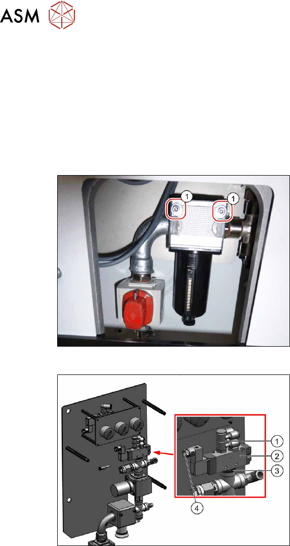
Fig.109: Screws fastening the inlet filter
► Remove the two screws (1) fastening
the inlet filter. This enables you to pull
the whole unit down a little and
provides better access.
Fig.110: Removing the valve
► Unplug the electrical connection(4)
from the valve(2).
► Unplug the pneumatic connections
from the distributor(1)
.
► Remove the screwed connection(3)
from the underside of the valve.
► Carefully remove the valve, together
with the distributor.
► Dismantle the distributor from the
valve.
Installation
Follow the removal instructions in reverse order for installation. Also observe the following instruc-
tions:
► Seal the compressed air system with sealant. Observe the instructions in section 5.4 "Sealing
the Pneumatic Screwed Connections" [}88].
5 Pneumatic System
5.8 Replacing the pneumatics assembly at location 1
Service Manual SIPLACE X-Series S (from Hxxxx) 01/2021 93
5.8 Replacing the pneumatics assembly at location 1
Parts, equipment and tools
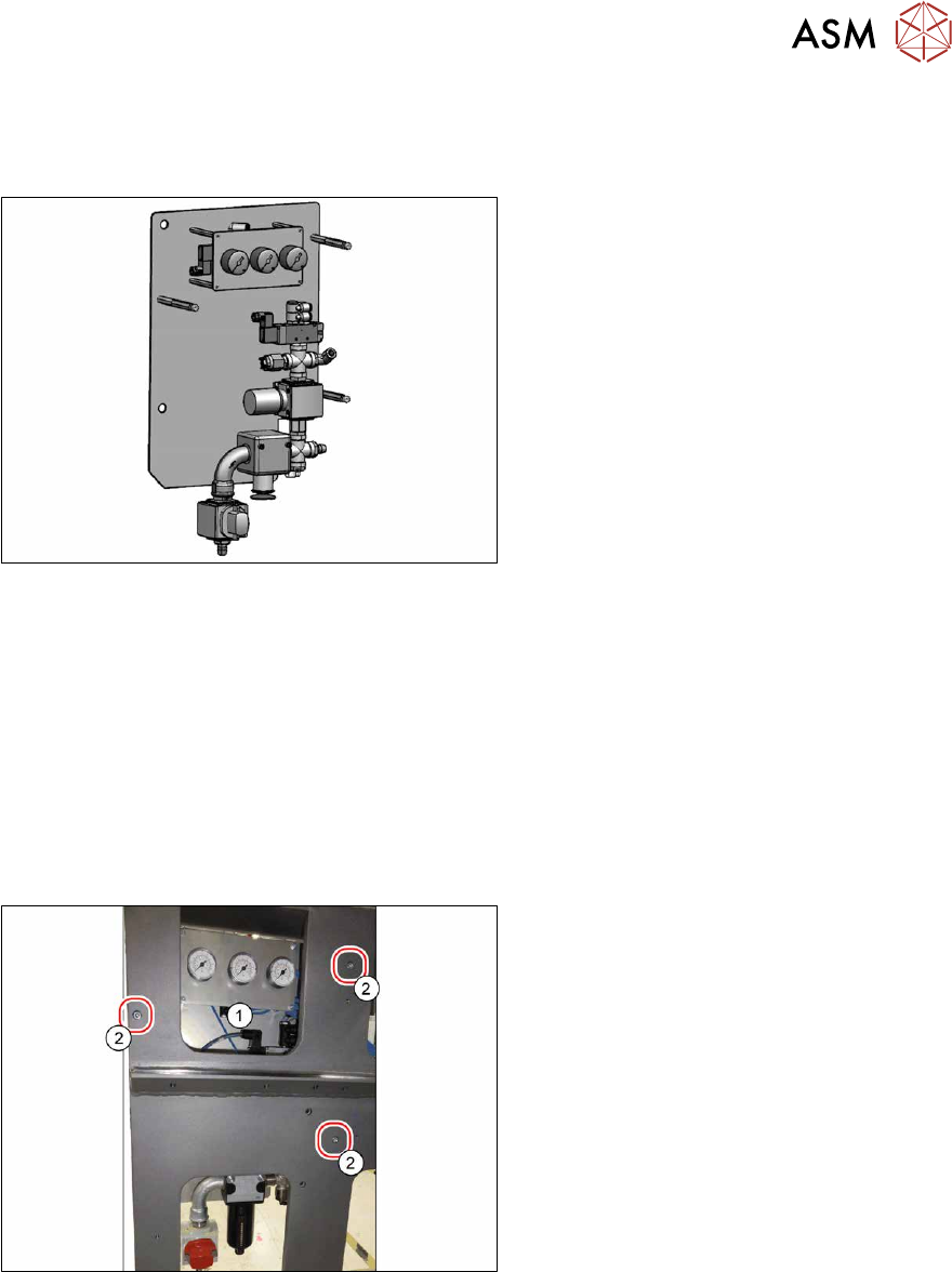
Fig.111: Pneumatics assembly X-Series [03089643‑xx]
●
Pneumatics assembly X-Series
[03089643‑xx]
●
Sealant (see 5.4 "Sealing the Pneu-
matic Screwed Connections" [}88])
Removal
► Switch off the machine, disconnect it from the power supply and secure it to prevent
unauthorized reactivation.
1.2 "Preparatory work..." [}16]
► Switch off the compressed air supply and then disconnect the machine from the compressed
air supply.
5.2 "Disabling the compressed air supply" [}86]
► To do this, remove the screws fastening the side cover and remove this cover.
5.5 "Dismantling the Lower Side Cover" [}88]
Fig.112: Pressure control valve
► Remove the three screws(2) fastening
the pneumatics assembly(1)
.
► Unplug all electrical and pneumatic
connections from the pneumatics
assembly. You may want to mark the
positions of these connections to make
clear assignment easier later on.
► Carefully remove the pneumatics unit.
Installation
Follow the removal instructions in reverse order for installation. Also observe the following instruc-
tions:
► Seal the compressed air system with sealant. Observe the instructions in section 5.4 "Sealing
the Pneumatic Screwed Connections" [}88] in connection with this.
5 Pneumatic System
5.9 Replacing the proportional controller (pressure control valve) (location 4)
94 Service Manual SIPLACE X-Series S (from Hxxxx) 01/2021
5.9 Replacing the proportional controller (pressure control
valve) (location 4)
Parts
Fig.113: Proportional controller [03152704‑xx] (version2)
●
Proportional controller Sentronic-LP
[03152704Sxx] (replaces
[03065425‑xx])
NOTICE!
The proportional controller is supplied
with the latest parameters preset. Sub-
sequent programming is not possible.
.
●
Adapter plate, top [03136076‑xx]
●
Adapter plate bottom [03138952‑xx]
●
In vacuum mode, when only one proportional controller is fitted:
Sealing plate for prop. valve (with O-rings) [03113039-xx]
●
3x ISO4762-M4x55-A2–70 [03147182‑xx] (contained in [03152704Sxx])
(replaces 3x ISO4762-M4x70-A2-70 [03082432-xx] for the old proportional controller
[03065425‑xx])
Equipment and tools
●
Isoflex Topas NCA 52, can 1kg [00328369‑xx]
or
Isoflex Topas NCA 52, tube 50 g [00330850‑xx]
●
Loctite 241 [02101037‑xx]
You might require additional documents:
●
Assembly instructions "Option Vacuum Pump SIPLACE X-Series S from Hxxxx " [DEEN:
00198599‑xx]
Overview
Fig.114: Overview proportional controller (version 1)
1. to 4.: Location 1 to 4
5.: Proportional controller top and bottom
NOTICE!
Only one proportional controller is fit-
ted for vacuum pump mode (all
heads).
When converting to compressed air
mode (Twin and CPP), you need to fit
a second proportional controller.
Also read the assembly instructions for
the vacuum pump.
.