MDS-C1-SPA Series INSTRUCTION MANUALib1500152(eng)a.pdf - 第101页
4. Spindle Adjustment 4 - 10 (4) Spindle control input 4 Name Details F E D C B A 9 8 7 6 5 4 3 2 1 0 hsp ovr deg ss3 ss2 ss1 Emg bit Details 0 E mg Emergency stop 1 ss1 Speed selection1 2 ss2 Speed selection2 3 ss3 Spee…
4. Spindle Adjustment
4 - 9
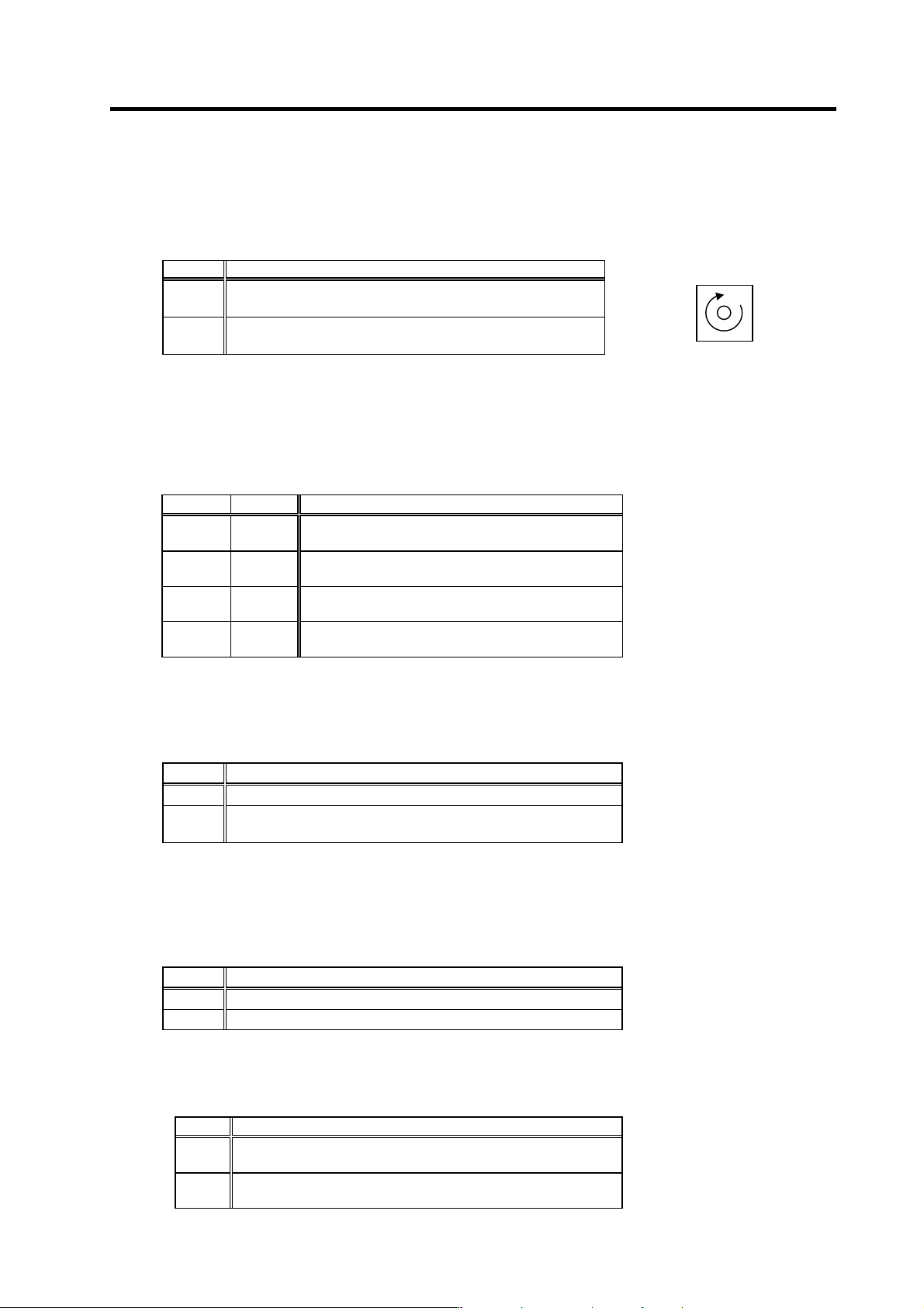
bit9. Reverse run start command (SRI)
This is an operation command. The speed command must also be designated to rotate the motor.
If the orientation command is input, the orientation operation will have the priority.
This is validated when closi ng (ON) the circuit between 2 pin (SRI) and 19 pin (CES1) of CN10.
SRN Explanation
1 (ON)
The motor rotates in the clockwise direction (CW) looking from the
shaft at the commanded speed.
0 (OFF)
The motor decelerates to a stop.
After stopping, the drive unit's power module turns OFF.
(Note 1) If READY ON signal is turned OFF, both forward run and reverse run signals will not be accepted.
(Note 2) If both forward run signal and reverse run signal are turned ON, the motor will be stopped regardless of the value
of the speed command. In this case, note that the power is supplied to the motor even if the motor is stopped.
bitA. Indexing forward run command (WRN)
bitB. Indexing reverse run command (WRI)
This is valid when the orientation start command is ON.
WRI WRN Explanation
1
(ON)
1
(ON)
Setting prohibited.
0
(OFF)
1
(ON)
Indexing is carried out in the counterclockwise (CCW)
direction looking from the motor end.
1
(ON)
0
(OFF)
Indexing is carried out in the clockwise (CW) direction
looking from the motor end.
0
(OFF)
0
(OFF)
Indexing is not carried out.
For the related parameters, refer to the adjustment for the indexing control in the adjustment procedure for each control.
bitC. Orientation start command (ORC)
This signal is used to start orientation. Orientation has a priority when the orientation start
command is input.
ORC Explanation
1 (ON) Orientation starts regardless of the run command (SRN, SRI).
0 (OFF)
When a run command (SRN, SRI) is selected, the rotation starts again
at the commanded speed.
For the related parameters, refer to the adjustment for the orientation control in the adjustment procedure for each control.
bitD. L coil selection command (LCS)
This command is input to select the coil method for changing the coil. Note that coil changeover is
not possible when orientation is commanded. The coil is fixed when the orientation command is
input.
LCS Explanation
1 (ON) The low-speed command is selected.
0 (OFF) The high-speed command is selected.
bitE. Sub-motor selection command (Msl)
This command input signal is used to select sub-motor when changing over 1-drive unit 2-motor
(spindle motor/general purpose motor).
MS Explanation
1
(ON)
Sub-motor is selected.
0
(OFF)
Main-motor is selected.
Spindle motor rotation direction
Clockwise direction
4. Spindle Adjustment
4 - 10
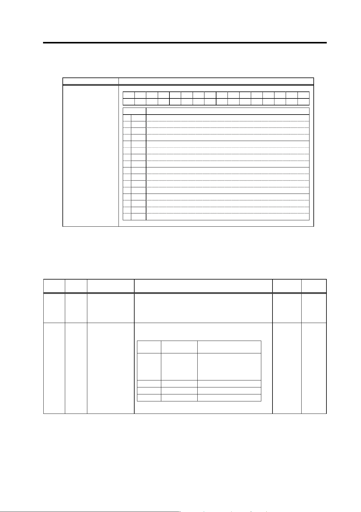
(4) Spindle control input 4
Name Details
F E D C B A 9 8 7 6 5 4 3 2 1 0
hsp ovr deg
ss3 ss2 ss1 Emg
bit Details
0 Emg Emergency stop
1 ss1 Speed selection1
2 ss2 Speed selection2
3 ss3 Speed selection3
4
5 deg Digital speed command valid
6 ovr Override input
7 hsp S-analog speed synchronous tapping
8
9
A
B
C
D
E
F
Spindle control input 4
bit0. Emergency stop (Emg)
This signal turns ON when the emergency stop input signal is opened (OFF). When this signal is
opened (OFF) during motor rotation, the motor will decelerate to stop.
Related spindle parameters
No. Abbr. Parameter name Details
Setting
range
Standard
SP129
to
SP140
HI01
to
HI12
General-purpose
input selection 1
to
General-purpose
input selection 12
Set the following value in any one of these parameters when
using the emergency stop.
"10": Emergency stop (emg) 0 to 21 0
SP192 FNC0
Function selection at
emergency stop
Set the state of alarm output and ready-ON output at the
emergency stop.
Setting
value
Alarm output Ready-ON output
0 Not available Turned OFF when the
amount of time set in
SP055(SETM) has passed
after the motor stopped
1 Available Same as above
2 Not available Continued ON
3 Available Continued ON
Note) When the ready-ON input signal is turned OFF, the
ready-ON signal is turned OFF regardless of the settings above.
0 to 1000 0
4. Spindle Adjustment
4 - 11
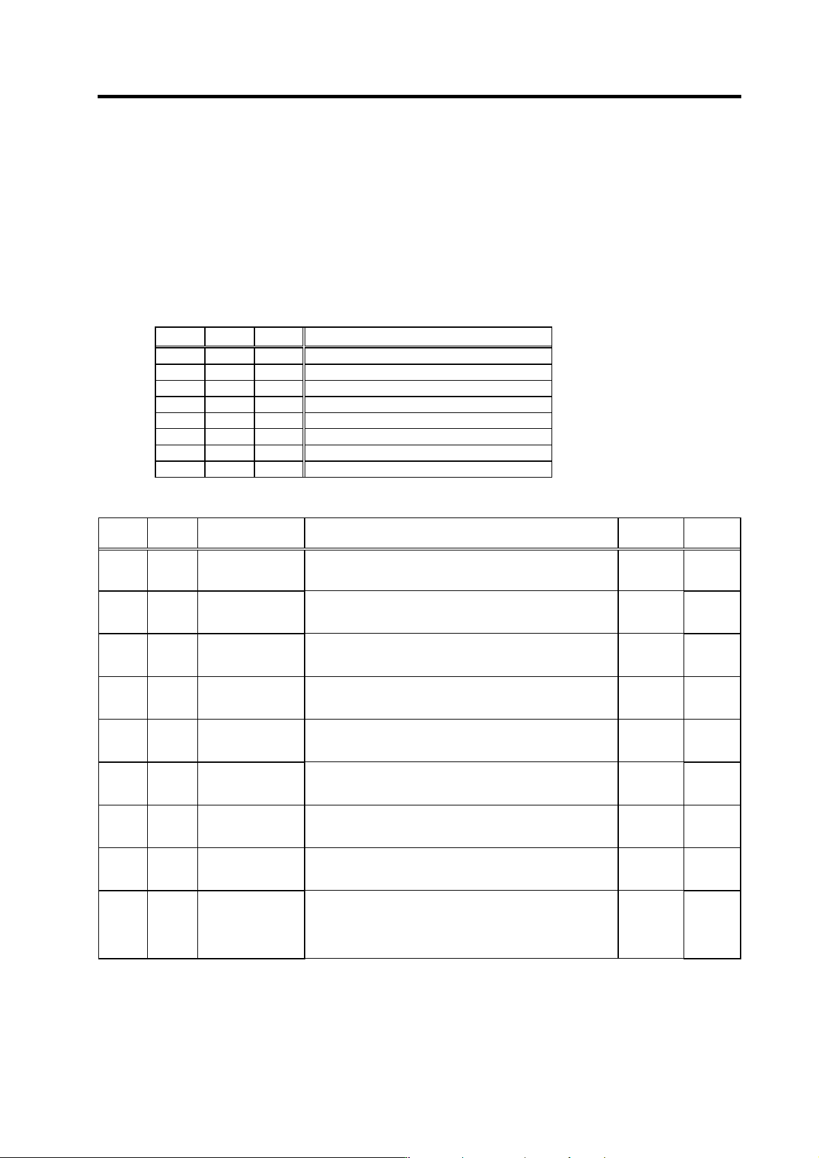
bit1. Speed selection 1 (ss1)
bit2. Speed selection 2 (ss2)
bit3. Speed selection 3 (ss3)
This is used to determine the speed command with three inputs.
By using the combination of ss1 to 3 input, set the speed command value to the value set in SP162
to SP169.
Note that, however, if the value of SP162 is "0" and ss1 to 3 are all OFF, the speed command is
the input given by the regular analog voltage.
ss3 ss2 ss1 Speed setting value
0 0 0 SP162
0 0 1 SP163
0 1 0 SP164
0 1 1 SP165
1 0 0 SP166
1 0 1 SP167
1 1 0 SP168
1 1 1 SP169
Related spindle parameters
No. Abbr. Parameter name Details
Setting
range
Standard
SP162 SS00 Speed setting 0
Regardless of whether the speed command mode is analog or
digital, the motor is run by the value set here when the
forward/reverse run signal is input.
0 to 32767
(r/min)
0
SP163 SS01 Speed setting 1
Set the motor speed command value when the speed selection
1 is assigned to the general-purpose input and the input is
turned ON.
0 to 32767
(r/min)
0
SP164 SS02 Speed setting 2
Set the motor speed command value when the sp eed selection
1, 2 or 1, 2, 3 are assigned to the general-purpose input and
only the speed selection 2 is turned ON.
0 to 32767
(r/min)
0
SP165 SS03 Speed setting 3
Set the motor speed command value when the speed selection
1, 2 or 1,2,3 are assigned to the general-pu rpose input and the
speed selection 1,2 are turned ON.
0 to 32767
(r/min)
0
SP166 SS04 Speed setting 4
Set the motor speed command value when the speed selection
1,2,3 are assigned to the general-purpose input and the speed
selection 3 is turned ON.
0 to 32767
(r/min)
0
SP167 SS05 Speed setting 5
Set the motor speed command value when the speed selection
1,2,3 are assigned to the general-purpose input and the speed
selection 1,3 are turned ON.
0 to 32767
(r/min)
0
SP168 SS06 Speed setting 6
Set the motor speed command value when the speed command
1,2,3 are assigned to the general-purpose input and the speed
selection 2,3 are turned ON.
0 to 32767
(r/min)
0
SP169 SS07
Speed setting 7
Set the motor speed command value when the speed selection
1,2,3 are assigned to the general-purpose input and the speed
selection 1,2,3 are all turned ON.
0 to 32767
(r/min)
0
SP129
to
SP140
HI01
to
HI12
General-purpose
input selection 1
to
General-purpose
input selection 12
Set the following value in any one of these parameters when
using the speed selection.
"11": Speed selection 1 (ss1)
"12": Speed selection 2 (ss2)
"13": Speed selection 3 (ss3)
0 to 21 0