MDS-C1-SPA Series INSTRUCTION MANUALib1500152(eng)a.pdf - 第109页
4. Spindle Adjustment 4 - 18 bit9. Motor in reverse run (SRIA) This signal turns ON while the start sig nal is input and the motor is rotating in the CW direction looking from the motor shaf t. This signal may turn ON an…
4. Spindle Adjustment
4 - 17
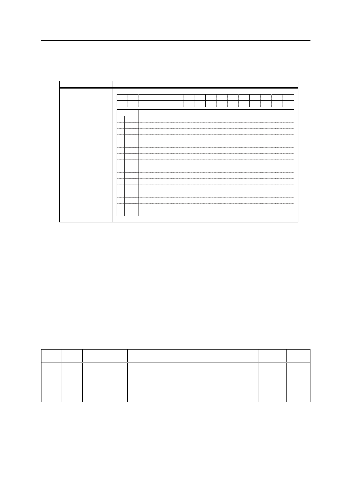
(3) Spindle control output 3
Name Details
F E D C B A 9 8 7 6 5 4 3 2 1 0
LCSA
ORCA
WRIA
WRNA
SRIA
SRNA
GR2A GR1A SC5A SC4A SC3A SC2A SC1A
bit Details
0
SC1A
Inputting spindle control mode selection command 1 signal
1
SC2A
Inputting spindle control mode selection command 2 signal
2
SC3A
Inputting spindle control mode selection command 3 signal
3
SC4A
Inputting spindle control mode selection command 4 signal
4
SC5A
Inputting spindle control mode selection command 5 signal
5
GR1A
Inputting gear selection command 1 signal
6
GR2A
Inputting gear selection command 2 signal
7
8
SRNA
Motor in forward run
9
SRIA
Motor in reverse run
A
WRNA
In forward run indexing
B
WRIA
In reverse run indexing
C
ORCA
In orientation start command signal
D
LCSA
L coil selected (when using the coil changeover motor)
E
MSA
In sub-motor selection (for 1-drive unit 2-motor changeover)
F
Spindle control output 3
bit0. Inputting spindle control mode selection command 1 signal (SC1A)
bit1. Inputting spindle control mode selection command 2 signal (SC2A)
bit2. Inputting spindle control mode selection command 3 signal (SC3A)
bit3. Inputting spindle control mode selection command 4 signal (SC4A)
bit4. Inputting spindle control mode selection command 5 signal (SC5A)
The respective signal turns ON when the spindle control mode selection command 1 to 5 is input.
bit5. Inputting gear selection command 1 signal (GR1A)
bit6. Inputting gear selection command 2 signal (GR2A)
The respective sign al turns ON when the gear selection command 1 or 2 is input.
bit8. Motor in forward run (SRNA)
This signal turns ON while the start signal is input and the motor is rotating in the CCW direction
looking from the motor shaft. This signal may turn ON and OFF if the motor speed is several r/min
or less.
No. Abbr. Parameter name Details
Setting
range
Standard
SP141
to
SP154
HO1e
to
HO6c
General-purpose
output selection
Open emitter 1 to
General-purpose
output selection
Open collector 6
Set the following value in any one of these parameters when
using the motor in forward run output.
“7”: Motor in forward run (SRNA)
0 to 23 0
4. Spindle Adjustment
4 - 18
bit9. Motor in reverse run (SRIA)
This signal turns ON while the start signal is input and the motor is rotating in the CW direction
looking from the motor shaft. This signal may turn ON and OFF if the motor speed is several r/min
or less.
No. Abbr. Parameter name Details
Setting
range
Standard
SP141
to
SP154
HO1e
to
HO6c
General-purpose
output selection
Open emitter 1 to
General-purpose
output selection
Open collector 6
Set the following value in any one of these parameters when
using the motor in reverse run output.
“8”: Motor in reverse run (SRIA)
0 to 23 0
bitA. In forward run indexing (WRNA)
bitB. In reverse run indexing (WRIA)
The corresponding output signal turns ON while forward run indexing (WRN) or reverse run
indexing (WRI) is input to the spindle drive unit. For the details, refer to the adjustment for the
indexing control in the adjustment procedure fo r each control.
bitC. In orientation start command signal (ORCA)
This signal turns ON while the orientation start command (ORC) is input to the spindle drive unit.
bit D. L coil selected (LCSA)
This signal turns ON while the L coil selection signal (LCA) is input to the spindle drive unit.
No. Abbr. Parameter name Details
Setting
range
Standard
SP141
to
SP154
HO1e
to
HO6c
General-purpose
output selection
Open emitter 1 to
General-purpose
output selection
Open collector 6
Set the following value in any one of these parameters when
using the L coil selected output.
“18”: L coil selected (LCSA)
0 to 23 0
bitE. In sub-motor selection (MSA)
This signal turns ON when selecting sub-motor with 1-drive unit 2-motor specifica t ion.
4. Spindle Adjustment
4 - 19
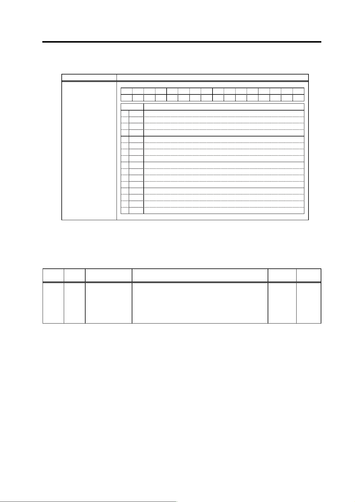
(4) Spindle control output 4
Name Details
F E D C B A 9 8 7 6 5 4 3 2 1 0
AL4 AL3 AL2 AL1
EMG
A
TLU
MTC WRCF MKC
ORCF
ZS US SD CD
bit Details
0
CD
Current detection
1
SD
Speed detection
2
US
Up-to-speed
3
ZS
Zero speed
4
ORCF
Orientation complete
5
6
MKC
Changing coil
7
WRCF
Index positioning completed
8
MTC
In changeover (for 1-drive unit 2-motor changeover)
9
A
TLU
Torque reach
B
EMGA
In emergency stop
C
AL1
Alarm code 1
D
AL2
Alarm code 2
E
AL3
Alarm code 3
F
AL4
Alarm code 4
Spindle control output 4
bit0. Current detection (CD)
This signal turns ON when the start signal (forward run, reverse run, orientation) is ON, and the
current flowing to the motor is approx. 110% or more of the rating. (The motor output (current)
guarantee value is 120% of the rating.)
No. Abbr. Parameter name Details
Setting
range
Standard
SP141
to
SP154
HO1e
to
HO6c
General-purpose
output selection
Open emitter 1 to
General-purpose
output selection
Open collector 6
Set the following value in any one of these parameters when
using the current detection output.
“12”: Current detection (CD)
0 to 23 0