MDS-C1-SPA Series INSTRUCTION MANUALib1500152(eng)a.pdf - 第132页
4. Spindle Adjustment 4 - 41 (c) Magnetic sensor An accurate gear ratio (pulley ratio) is required from the motor shaft to the detector rotary axis. Make sure that the correct number of gear te eth is set in SP025 (GRA1)…
4. Spindle Adjustment
4 - 40
(3) Confirming the default parameters
Set the orientation start(ORC) and orie ntation complete(ORCF) for the general-purpose
input/output. If there is a gear, set the gear selection 1,2(GR1,G R2) for the gene ral-purpose input.
And, set the default parameters for each detecto r used in orientation control.
(a) Motor PLG
Motor PLG orientation is possible only when the spindle and motor are coupled, or when they
are coupled 1:1 with gears (timing belt). The SP025 (GRA1) to SP032 (GRB4) parameters can
be set only to 1. The PLG with Z-phase must be mounted on the motor to be used.
(b) 1024p/rev encoder
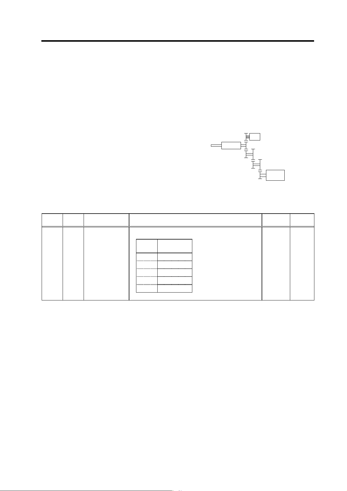
An accurate gear ratio (pulley ratio) is required from
the motor shaft to the encoder axis.
Make sure that the correct number of gear teeth is
set in SP025 (GRA1) to SP032 (GRB4).
SP025 to SP028=A × C × E
SP029 to SP032=B × D × F
Set the gear ratio (A:X) between the spindle and
encoder in SP096 (EGAR).
No. Abbr. Parameter name Details
Setting
range
Standard
Set the gear ratio between the spindle side and the detector
side (except for the motor PLG) as indicated below.
Setting
value
Gear ratio
(deceleration)
0 1 : 1
1 1 : 1/2
2 1 : 1/4
3 1 : 1/8
4 1 : 1/16
SP096 EGAR* Encoder gear ratio 0 to 4 0
Encode
r
XS
p
indle
Spindle
moto
r
A
BC
D E
F
Spindle configuration when using
spindle side detector
4. Spindle Adjustment
4 - 41
(c) Magnetic sensor
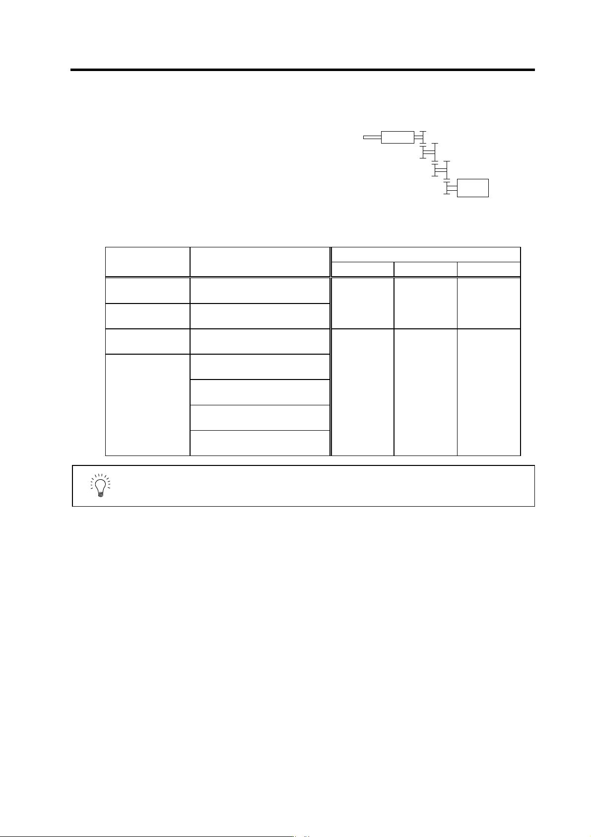
An accurate gear ratio (pulley ratio) is required from
the motor shaft to the detector rotary axis. Make sure
that the correct number of gear teeth is set in SP025
(GRA1) to SP032 (GRB1).
SP025 to SP028=A × C × E
SP029 to SP032=B × D × F
The SP123 (MGD0) to SP125 (MGD2) parameters
are set as shown below according to the magnetic
sensor type.
Parameter setting
Type Magnetic sensor type
SP123 (MGD0) SP124 (MGD1) SP125 (MGD2)
Standard
MAGNETIC SENSOR
BKO-C1810H01-3
High-speed standard
MAGNETIC SENSOR
BKO-C1730H01.2.6
542 768 384
High-speed compact
MAGNETIC SENSOR
BKO-C1730H01.2.9
MAGNETIC SENSOR
BKO-C1730H01.2.41
MAGNETIC SENSOR
BKO-C1730H01.2.42
MAGNETIC SENSOR
BKO-C1730H01.2.43
High-speed ring type
MAGNETIC SENSOR
BKO-C1730H01.2.44
500 440 220
POINT
When using the magnetic sensor, orient ation control cannot be carried out with
a machine having a gear ratio between the spindle motor and spi ndle exceeding
1:31.
S
p
indle
Spindle
moto
r
A
B C
D E
F
Spindle configuration when using
magnetic sensor
4. Spindle Adjustment
4 - 42
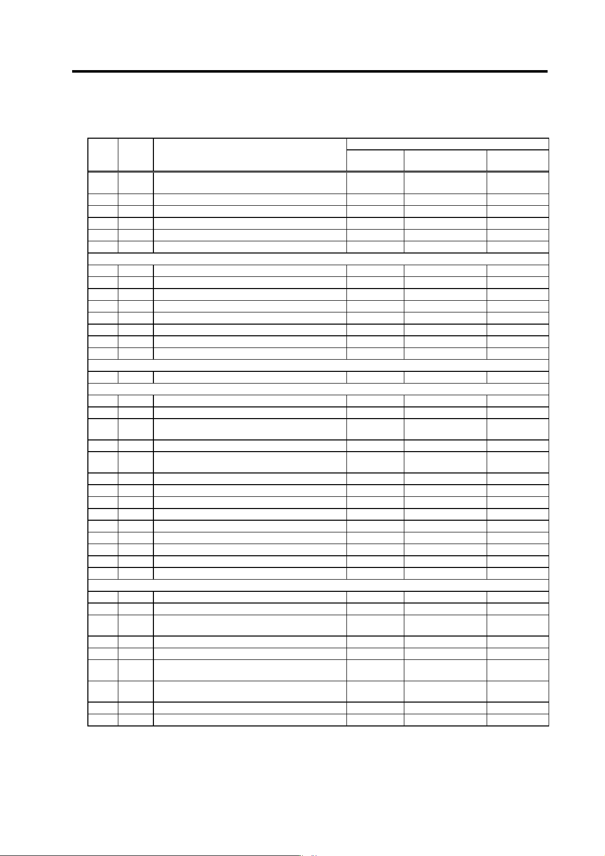
The default orientation control parameters for each detector are as shown below. Confirm that these
parameters are correctly set according to the machi ne specifications.
Default parameter settings for detector in use
No. Abbr. Parameter name
(a) Motor PLG (b) Encoder
(c) Magnetic
sensor
SP001 PGM*
Magnetic sensor and motor PLG orientation position
loop gain
100 - 100
SP002 PGE* Encoder orientation position loop gain - 100 -
SP004 OINP* Orientation in-position width 14 14 16
SP005 OSP Orientation mode speed clamp value 0 0 0
SP006 CSP* Orientation mode deceleration rate 20 20 20
SP007 OPST* In-position shift amount for orientation 0 0 0
SP025 GRA1 Spindle gear teeth count 1 1 * *
SP026 GRA2 Spindle gear teeth count 2 1 * *
SP027 GRA3 Spindle gear teeth count 3 1 * *
SP028 GRA4 Spindle gear teeth count 4 1 * *
SP029 GRB1 Motor shaft gear teeth count 1 1 * *
SP030 GRB2 Motor shaft gear teeth count 2 1 * *
SP031 GRB3 Motor shaft gear teeth count 3 1 * *
SP032 GRB4 Motor shaft gear teeth count 4 1 * *
SP037 SFNC5 Spindle function 5 0004 0001 0002
SP096 EGAR Encoder gear ratio - * -
SP097 SPECO Orientation specification 0000 0000 0000
SP098 VGOP
Speed loop gain proportional term in orientation
mode
63 63 63
SP099 VGOI Speed loop gain integral term in orientation mode 60 60 60
SP100 VGOD
Speed loop gain delay advance term in orientation
mode
15 15 15
SP101 DINP Orientation advance in-position width 16 16 16
SP102 OODR Excessive error value in orientation mode 32767 32767 32767
SP103 FTM Index positioning completion OFF time timer 200 200 200
SP104 TLOR Torque limit value after orientation completed 100 100 100
SP105 IQGO Current loop gain magnification 1 in orientation mode 100 100 100
SP106 IDGO Current loop gain magnification 2 in orientation mode 100 100 100
SP107 CSP2* Deceleration rate 2 in orientation mode 0 0 0
SP108 CSP3* Deceleration rate 3 in orientation mode 0 0 0
SP109 CSP4* Deceleration rate 4 in orientation mode 0 0 0
SP114 OPER* Orientation pulse miss check value 0 0 0
SP115 OSP2* Orientation control speed clamp value 2 0 0 0
SP116 OPYVR*
Minimum excitation value after changeover
(2nd minimum excitation rate)
0 0 0
SP117 ORUT* Fixed control constant 0 0 0
SP118 ORCT* Orientation control number of retry times 0 0 0
SP119 MPGH*
Orientation control position loop gain H coil
magnification
0 0 0
SP120 MPGL*
Orientation control position loop gain L coil
magnification
0 0 0
SP121 MPCSH* Orientation deceleration rate H coil magnification 0 0 0
SP122 MPCSL* Orientation deceleration rate L coil magnification 0 0 0
(Note 1) *: Set according to machine specifications, -: Setting irrelevant
(Note 2) For parameters with an asterisk * in the abbreviation, such as PGM*, if the settings of the parameters have been
changed with a personal computer, the parameters are validated without turning the spindle drive unit's power ON/OFF
immediately after the settings have been changed.