MDS-C1-SPA Series INSTRUCTION MANUALib1500152(eng)a.pdf - 第216页
Appendix 3. EMC Installation Guidelines A3 - 5 Appendix 3-4-3 Measures for operation board panel [1] Always connect the operation board and indicator with an earthing wire. [2] If the operation board panel has a door, us…
Appendix 3. EMC Installation Guidelines
A3 - 4
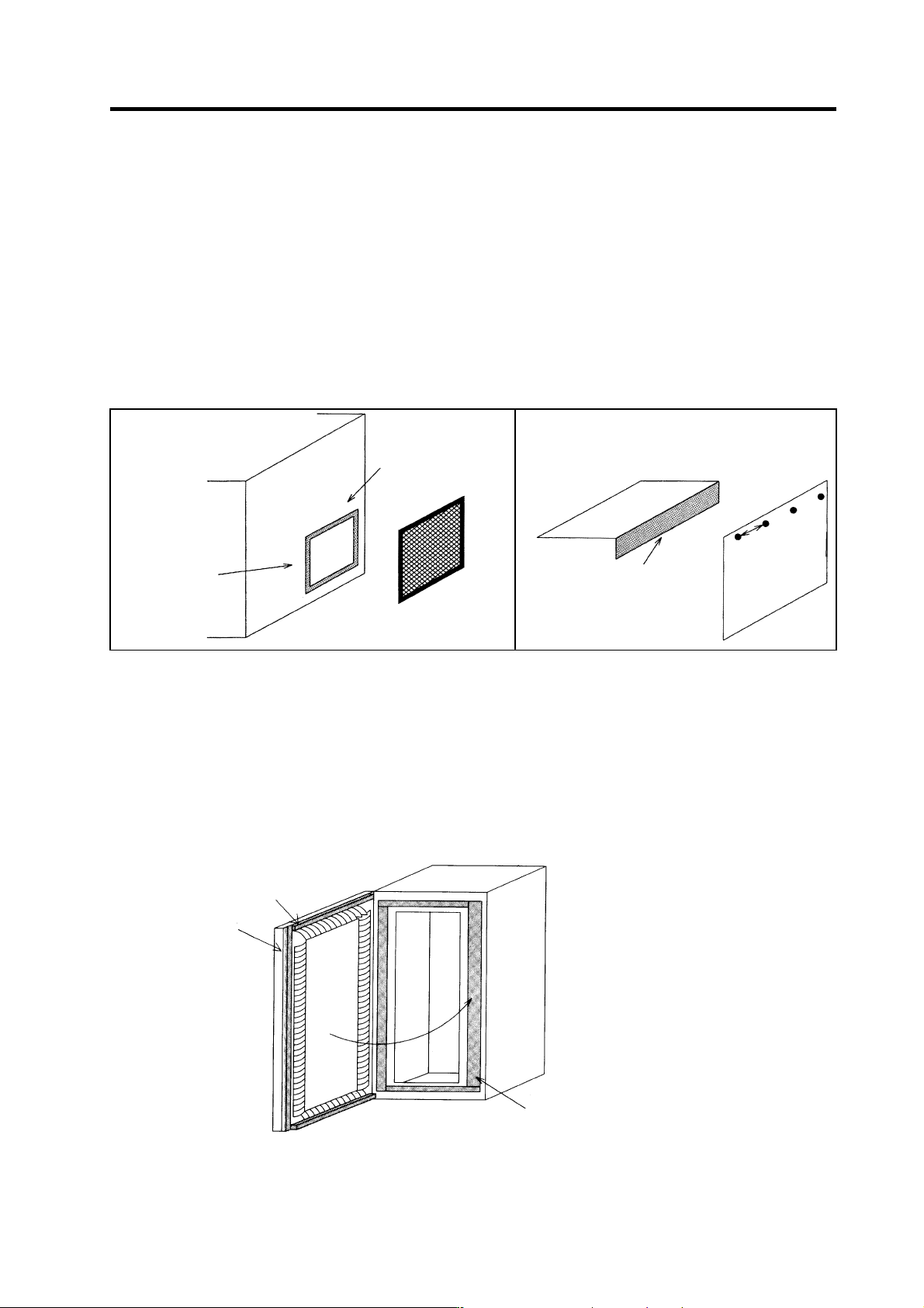
Appendix 3-4-1 Measures for control panel unit
[1] Use metal for all materials configuring the panel.
[2] For the joining of the top plate and side plates, etc., mask the contact surface with paint, and fix with
welding or screws.
In either case, keep the joining clearance to a max. of 20cm for a better effect.
[3] Note that if the plate warps due to the screw fixing, etc., creating a clearance, noise could leak from
that place.
[4] Plate the metal plate surface (with nickel, tin) at the earthing section, such as the earthing plate.
[5] The max. tolerable hole diameter of the openings on the panel surface, such as the ventilation
holes, must be 3cm to 5cm. If the opening exceeds this size, use a measure to cover it. Note that
even when the clearance is less than 3cm to 5cm, noise may still leak if the clearance is long.
Painting mask
Hole exceeding
3cm t o 5cm
∗
Provide elec t ri cal conduc tance
Painting mask
Max. joining
clearance 20cm
Appendix 3-4-2 Measures for door
[1] Use metal for all materials configuring the door.
[2] Use an EMI gasket or conductive packing for the contact between the door and control panel unit.
[3] The EMI gasket or conductive packing must contac t at a uniform and correct position of the metal
surface of the control panel unit.
[4] The surface of the control panel unit contacted with the EMI gasket or conductive packing must
have conductance treatment.
Example) Weld (or screw) a plate that is plated (with nickel, tin).
EMI gasket
Packing
Carry out conduct ance treatment on
sections that the EMI gasket contacts.
Door
Control panel
[5] As a method other than the above, the control panel unit and door can be connected with a plain
braided wire. In this case, the panel and door should be contacted at as many points as possible.
Exam
p
le
)
Appendix 3. EMC Installation Guidelines
A3 - 5
Appendix 3-4-3 Measures for operation board panel
[1] Always connect the operation board and indicator with an earthing wire.
[2] If the operation board panel has a door, use an EMI gasket or conductive packing between the door
and panel to provide electrical conductance in the same manner as the control panel.
[3] Connect the operation board panel and control panel with a sufficiently thick and short earthing
wire.
Refer to the "EMC INSTALLATION GUIDELINES" BNP-B2230 for the NC for more details.
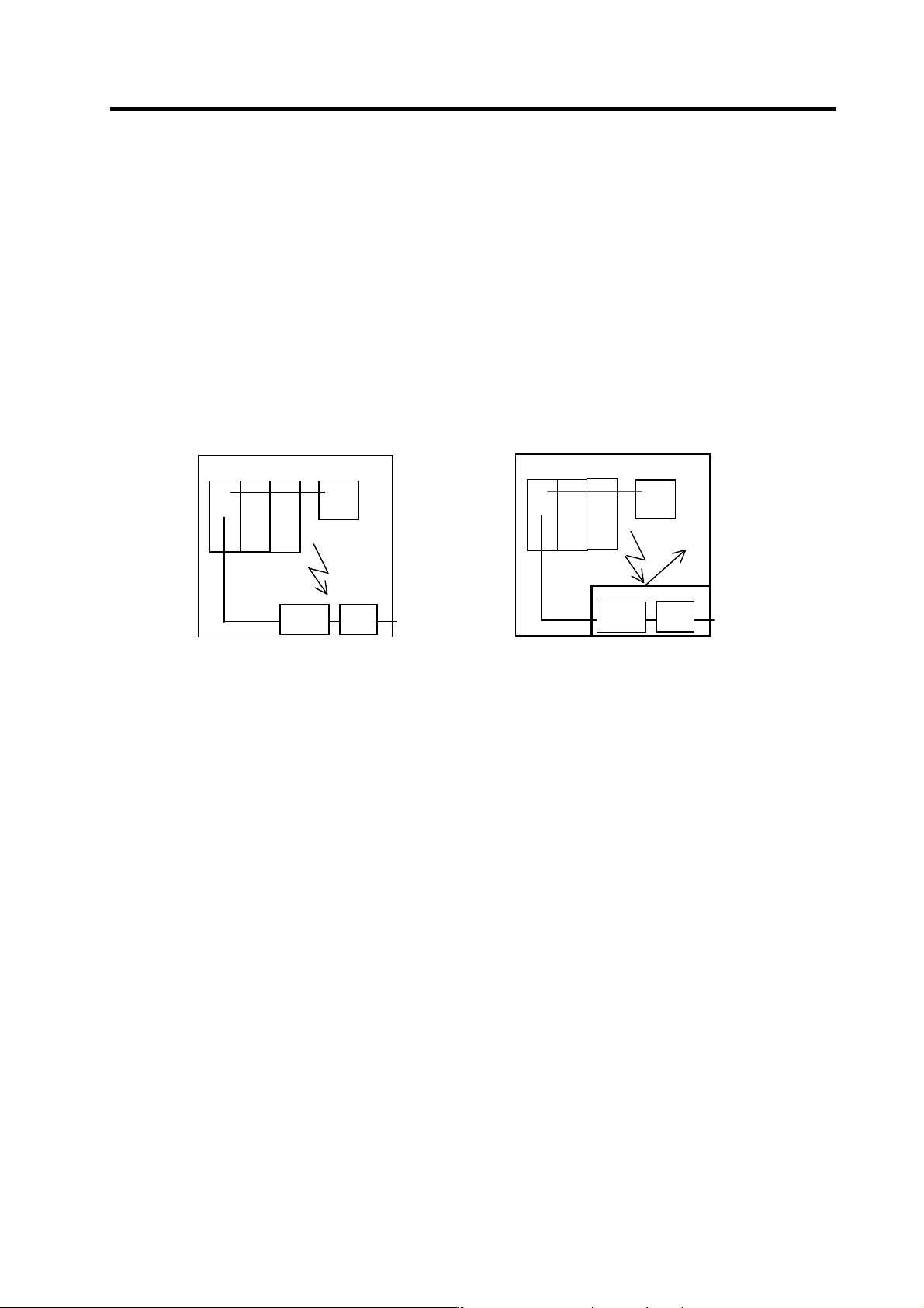
Appendix 3-4-4 Shielding of the power supply input section
[1] Separate the input power supply section from other parts in the control panel so that the input
power supply cable will not be contaminated by radiated noise.
[2] Do not lead the power line through the panel without passing it through a filter.
The power supply line noise is eliminated
by the filter, but cable contains noise again
because of the noise radiated in the control
panel.
Use a metal plate, etc., for the shielding
partition. Make sure not to create a
clearance.
Drive unit
Power
line filter
Breaker
Control panel
A
C input
Radiated
noise
Drive unit
Power
line filter
Breaker
Control panel
A
C input
Radiated
noise
Shielding
plate
Appendix 3. EMC Installation Guidelines
A3 - 6
Appendix 3-5 Measures for various cables
The various cables act as antennas for the noise and discharge the noise externally. Thus appropriate
treatment is required to avoid the noise.
The wiring between the drive unit and motor act as an extremely powerful noise source, so apply the
following measures.
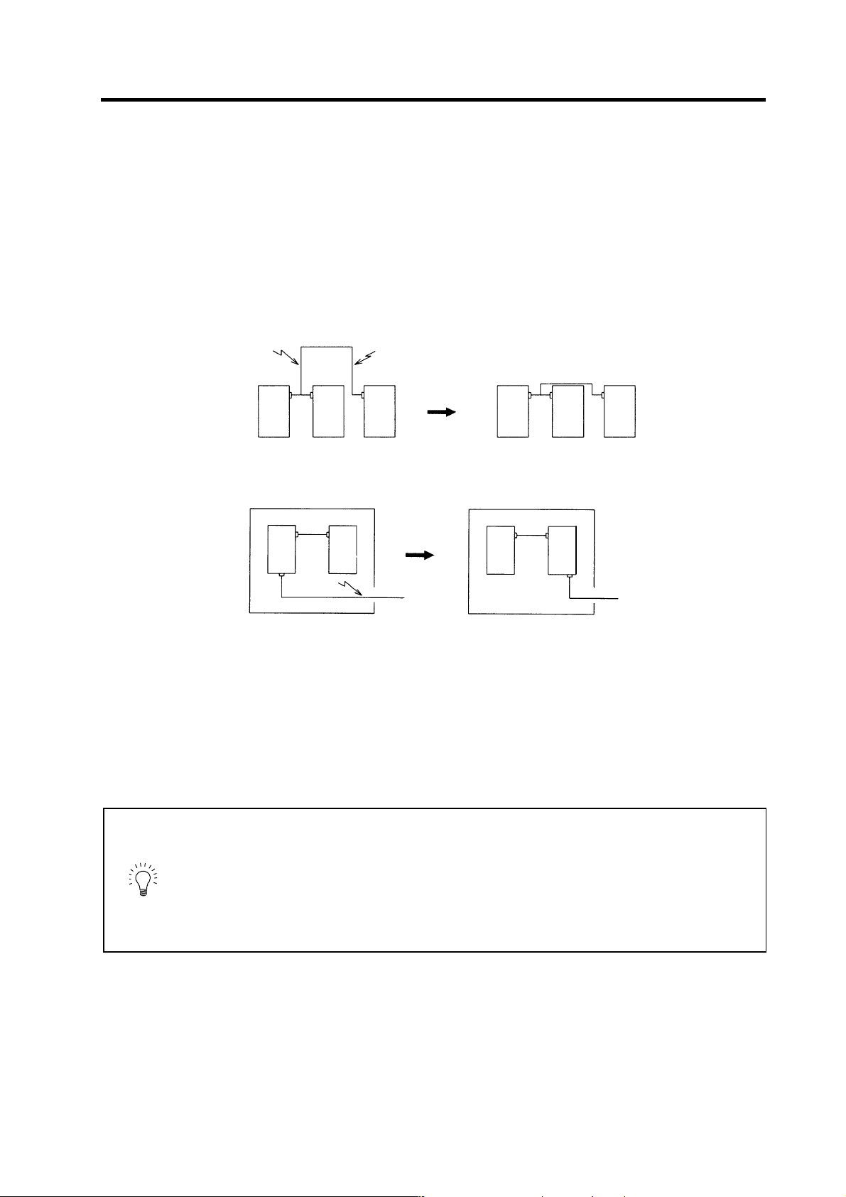
Appendix 3-5-1 Measures for wiring in panel
[1] If the cables are led unnecessarily in the panel, they will easily pick up the radiated noise. Thus,
keep the wiring length as short as possible.
Device Device Device Device Device Device
Noise Noise
[2] The noise from other devices will enter the cable and be discharged externally, so avoid internal
wiring near the openings.
Device
Device
Device
Device
Noise
Control panel
Control panel
[3] Connect the control device earthing terminal and earth ing plate with a thick wire. Take care to the
leading of the wire.
Appendix 3-5-2 Measures for shield treatment
Common items
Use of shield clamp fittings is recommended for treating the shields. The fittings are available as options,
so order as required. (Refer to section "Appendix 3-6-1 Shield clamp fitting".)
Clamp the shield at a position within 10cm from the panel lead out port.
POINT
1. When leading the cables, including the grounding wire (FG), outside of the
panel, clamp the cables near the panel outlet (recommendation: within
10cm).
2. When using a metal duct or conduit, the cables do not need to be clamped
near the panel outlet.
3. When leading cables not having shields outside the panel, follow the
instructions given for each cable. (Installation of a ferrite core, etc., may be
required.)