MDS-C1-SPA Series INSTRUCTION MANUALib1500152(eng)a.pdf - 第116页
4. Spindle Adjustment 4 - 25 bitA. Torque reach (TLU) This signal turns ON when the sta rt command is input and the torque command in the drive unit reaches to the clamp value. Related spindle parameters No. Abbr . Param…

4. Spindle Adjustment
4 - 24
bit7. Index positioning completed (WRCF)
This signal turns ON during indexing operation when the spindle position reaches the in-position
range in respect to the target stop position. Once this signal turns ON it will remain ON regardless
of the spindle position until the orientation signal turns OFF or the next indexing operation signal is
input.
This signal will turn OFF for the time set with paramet er SP103 (FTM ) when the indexing o peration
signal is input even if the current stop point and the next indexing position are in the in-position
range.
For the details, refer to the adjustment for the indexing control in the adjustment procedure for
each control.
Related spindle parameter
No. Abbr. Parameter name Details
Setting
range
Standard
SP103 FTM* Index positioning
completion OFF time
timer
Set the time for forcedly turn OFF the index positioning
completion signal (different from the orientation completion
signal) after the leading edge of the indexing start signal.
0 to 10000
(ms)
200
SP141
to
SP154
HO1e
to
HO6c
General-purpose
output selection
Open emitter 1 to
General-purpose
output selection
Open collector 6
Set the following value in any one of these parameters when
using the index positioning completed output.
“2”: Index positioning completed (WRCF)
0 to 23 0
bit8. In 1-drive unit 2-motor changeover (MTC)
This signal turns ON during motor changeover with 1-drive unit 2-motor specification.
No. Abbr. Parameter name Details
Setting
range
Standard
SP141
to
SP154
HO1e
to
HO6c
General-purpose
output selection
Open emitter 1 to
General-purpose
output selection
Open collector 6
Set the following value in any one of these parameters when
using the in changeover (for 1-drive unit 2-motor changeover)
output.
“17”: In changeover
(for 1-drive unit 2-motor changeover) (MTC)
0 to 23 0

4. Spindle Adjustment
4 - 25
bitA. Torque reach (TLU)
This signal turns ON when the start command is input and the torque command in the drive unit
reaches to the clamp value.
Related spindle parameters
No. Abbr. Parameter name Details
Setting
range
Standard
SP141
to
SP154
HO1e
to
HO6c
General-purpose
output selection
Open emitter 1
to
General-purpose
output selection
Open collector 6
Set the following value in any one of these parameters when
using the torque reach output.
“3”: Torque reach (TLU)
0 to 23 0
bitB. In emergency stop (EMGA)
This signal turns ON when the emergency stop input is turned ON.
Related spindle parameters
No. Abbr. Parameter name Details
Setting
range
Standard
SP141
to
SP154
HO1e
to
HO6c
General-purpose
output selection
Open emitter 1
to
General-purpose
output selection
Open collector 6
Set the following value in any one of these parameters when
using t the in emergency stop output.
“10”: In emergency stop (EMGA)
0 to 23 0
4. Spindle Adjustment
4 - 26
bitC. Alarm code output1 (AL1)
bitD. Alarm code output2 (AL2)
bitE. Alarm code output3 (AL3)
bitF. Alarm code output4 (AL4)
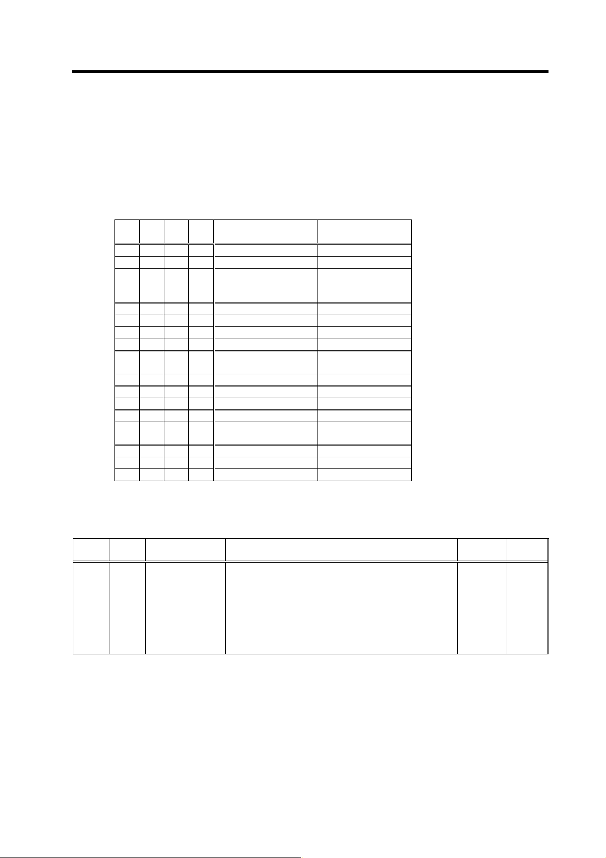
When an alarm occurs in the drive unit, this signal outputs the cont ent of the alarm that occu rred in
a combination of 4bit.
Even if the unit is normal, this signal may turn ON for 1 second after the power i s turned ON.
AL4 AL3 AL2 AL1 Alarm content
Spindle drive unit
7-segment display
0 0 0 0 No alarm (normal) -
0 0 0 1 Motor overheat 46
0 0 1 0
Excessive speed
deviation
23
0 0 1 1 Overspeed 31
0 1 0 0 Overcurrent 32
0 1 0 1 Overload 50
0 1 1 0 Emergency stop E7
0 1 1 1
Spindle drive unit side
alarm other than above
10 to 5F
1 0 0 0 Power module error 61
1 0 0 1
Phase failure detection
67
1 0 1 0
Ground fault detection
69
1 0 1 1 Main circuit error 6C
1 1 0 0
Instantaneous
/ external emergency stop
71
1 1 0 1 Overvoltage 75
1 1 1 0 No signal 82
1 1 1 1 Other alarms 60~
1: Output ON
0: Output OFF
Related spindle parameters
No. Abbr. Parameter name Details
Setting
range
Standard
SP141
to
SP154
HO1e
to
HO6c
General-purpose
output selection
Open emitter 1
to
General-purpose
output selection
Open collector 6
Set the following value in any one of these parameters when
using t the alarm code 1 to 4.
Make sure that all of these four output are set to any parameter
No.
“20”: Alarm code output1 (AL1)
“21”: Alarm code output2 (AL2)
“22”: Alarm code output3 (AL3)
“23”: Alarm code output4 (AL4)
0 to 23 0