MDS-C1-SPA Series INSTRUCTION MANUALib1500152(eng)a.pdf - 第130页
4. Spindle Adjustment 4 - 39 4-3-3 Adjusting the orientation control (1) Necessary input/output 1) Input: [1] Orientation start command (ORC) Connect to any one of the general-purp ose inputs [2] Multi-point orientation …
4. Spindle Adjustment
4 - 38
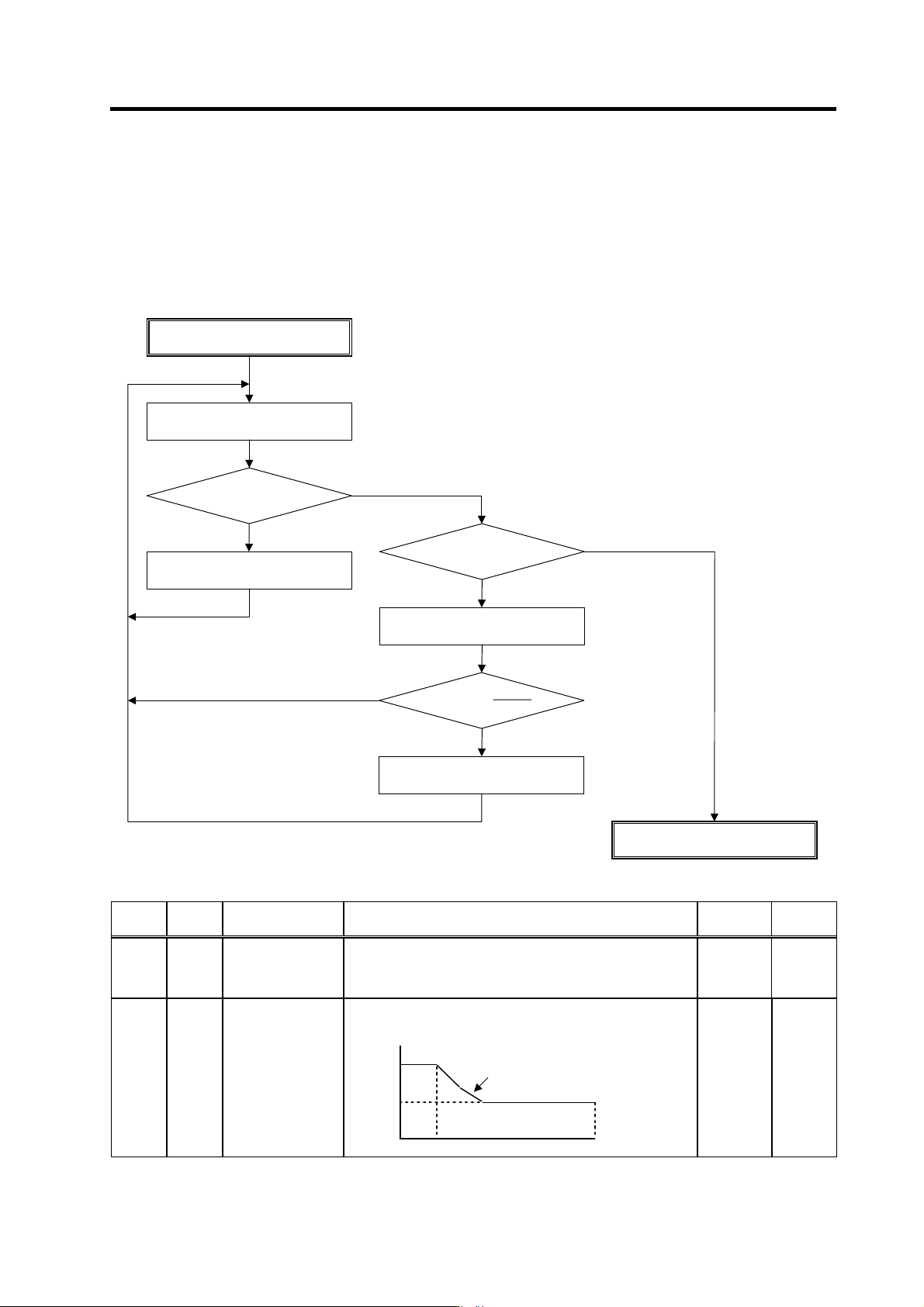
(9) Adjusting deceleration time
When the deceleration time "td" is significantly different from the acceleration time "ta" (td < 0.95 × ta,
1.1 × 1a < td) and no problem with the a cceleration time, adjust the deceleration time by cha nging
the setting of the parameter SP087(DIQM). In cases, however, where the variable torque
characteristic cannot be lowered to the SP087 le vel, adjust by changing the setting of the parameter
SP088(DIQN).
No. Abbr. Parameter name
Details
Setting
range
Standard
SP087 DIQM* Target value of
variable torque limit
magnification at
deceleration
Set the minimum value of variable torque limit at deceleration. 0 to 150
(%)
75
Set the speed where the torque limit value at deceleration
starts to change.
Torque limit
Inversely proportional to
speed
SP088 DIQN*
Speed for starting
change of variable
torque limit
magnification at
deceleration
100%
SP087
SP088 SP017 Speed
0 to 32767
(r/min)
3000
Adjusting SP087, SP088
td > 1.1 × ta?
SP087, SP088 adjustment completed
Increase SP087 by +5.
YES
NO
Measure acceleration/deceleration
waveform at high speed
td < 0.95 × ta?
Increase SP087 by –5.
YES
NO
SP087<100 × – ?
SP088
SP017
Increase SP088 by –500.
YES
NO
4. Spindle Adjustment
4 - 39
4-3-3 Adjusting the orientation control
(1) Necessary input/output
1) Input:
[1] Orientation start command (ORC)
Connect to any one of the general-purpose inputs
[2] Multi-point orientation positioning data (R1 to R12)
Connect when changing to an arbitrary stop position from outside during encoder
orientation or motor PLG orientation
2) Output: Orientation complete (ORCA)
Connect to any one of the general-purpose outputs
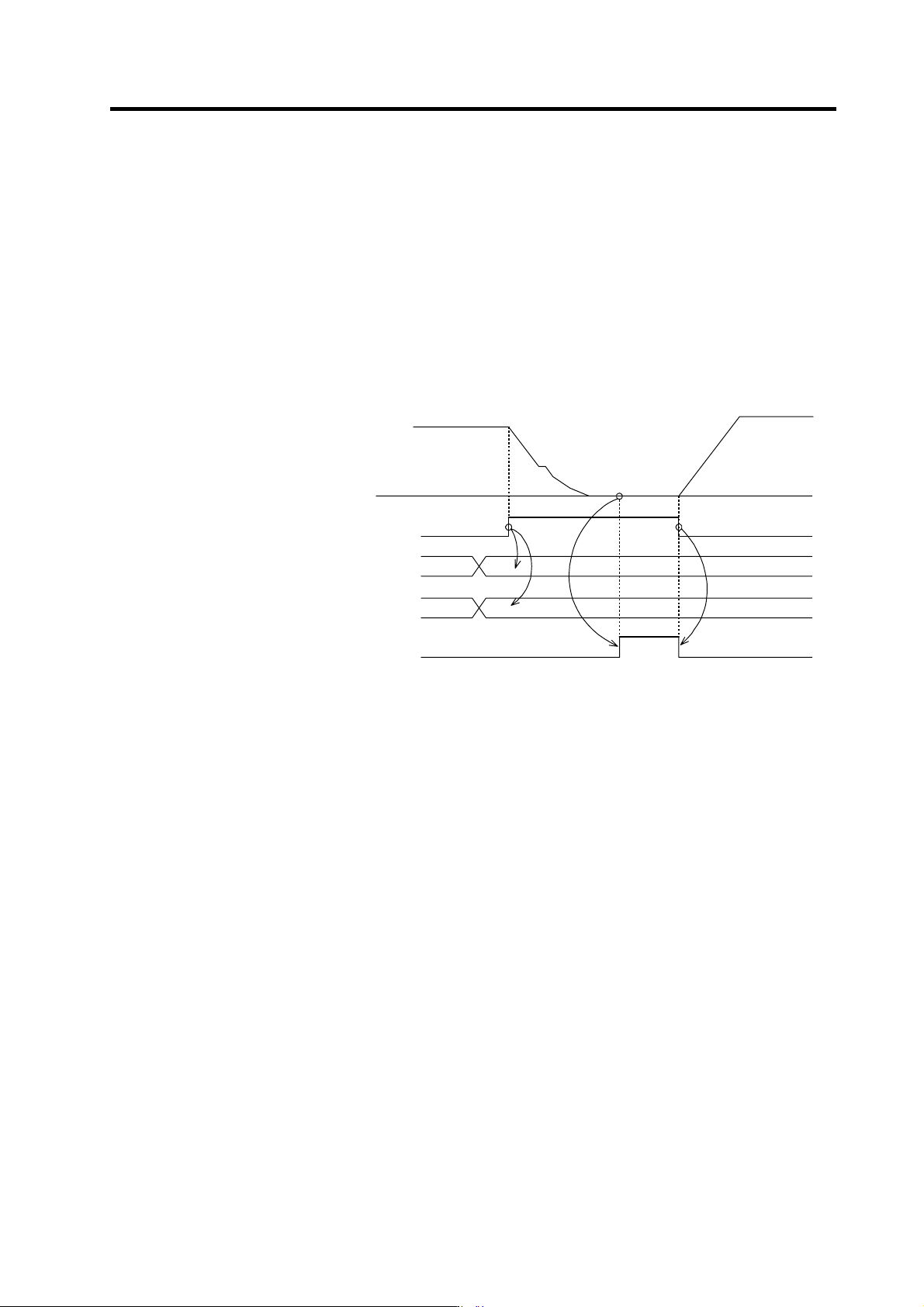
(2) Operation sequence
Motor speed
Gear selection command
12-bit multi-point orientation command
Orientation start command
Orientation complete output
1) The 12-bit multi-point orientation command (R1 to R12) is read at the rising edge of the
orientation start command (ORC) and must be changed before turning the orientation start
command ON.
2) The gear selection com mand (GR1, GR2) will be valid at all times eve n after the orientation start
command has been turned ON. Change the gear selection command before turning the
orientation start command ON and keep it ON until the orientation start command is turned
OFF.
4. Spindle Adjustment
4 - 40
(3) Confirming the default parameters
Set the orientation start(ORC) and orie ntation complete(ORCF) for the general-purpose
input/output. If there is a gear, set the gear selection 1,2(GR1,G R2) for the gene ral-purpose input.
And, set the default parameters for each detecto r used in orientation control.
(a) Motor PLG
Motor PLG orientation is possible only when the spindle and motor are coupled, or when they
are coupled 1:1 with gears (timing belt). The SP025 (GRA1) to SP032 (GRB4) parameters can
be set only to 1. The PLG with Z-phase must be mounted on the motor to be used.
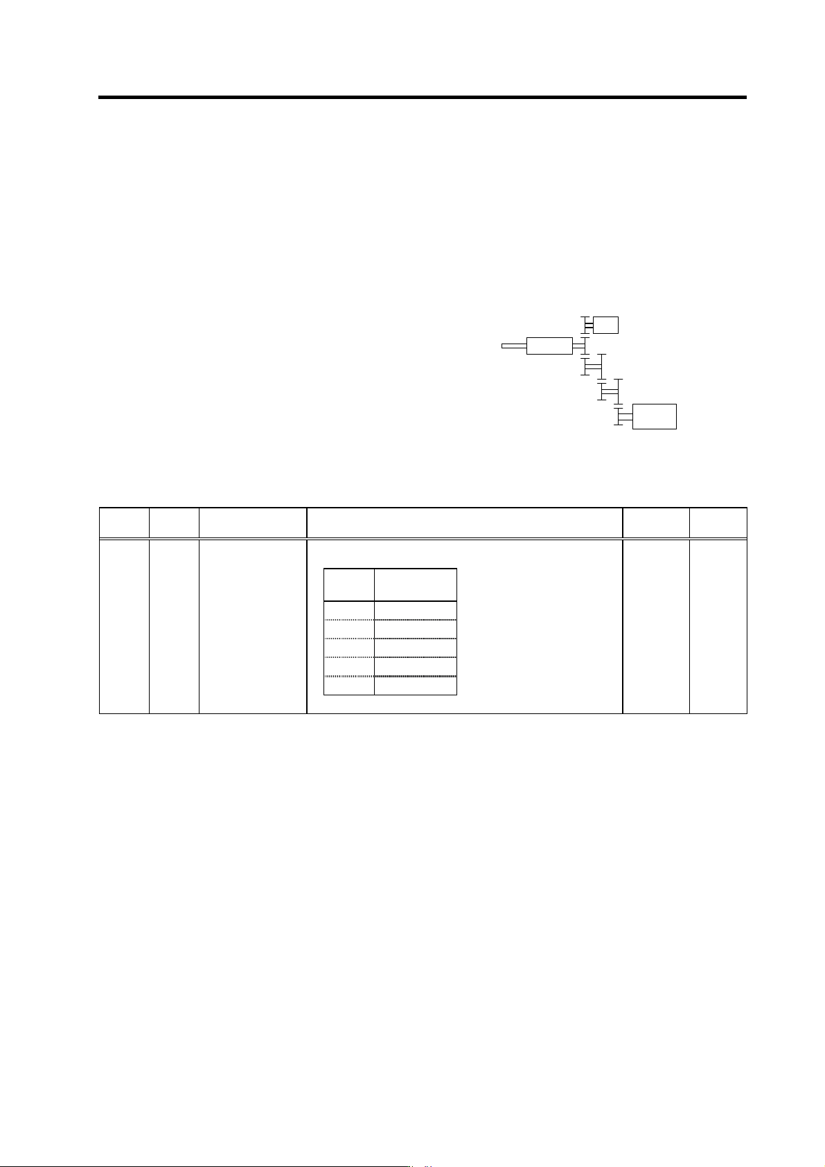
(b) 1024p/rev encoder
An accurate gear ratio (pulley ratio) is required from
the motor shaft to the encoder axis.
Make sure that the correct number of gear teeth is
set in SP025 (GRA1) to SP032 (GRB4).
SP025 to SP028=A × C × E
SP029 to SP032=B × D × F
Set the gear ratio (A:X) between the spindle and
encoder in SP096 (EGAR).
No. Abbr. Parameter name Details
Setting
range
Standard
Set the gear ratio between the spindle side and the detector
side (except for the motor PLG) as indicated below.
Setting
value
Gear ratio
(deceleration)
0 1 : 1
1 1 : 1/2
2 1 : 1/4
3 1 : 1/8
4 1 : 1/16
SP096 EGAR* Encoder gear ratio 0 to 4 0
Encode
r
XS
p
indle
Spindle
moto
r
A
BC
D E
F
Spindle configuration when using
spindle side detector