MDS-C1-SPA Series INSTRUCTION MANUALib1500152(eng)a.pdf - 第42页
2. Wiring and Connection 2 - 14 2-4 Motor and detector connection 2-4-1 Connection of the spindle motor Refer to each motor specifications for details on the motor side connection destination, specifications and outline,…
2. Wiring and Connection
2 - 13
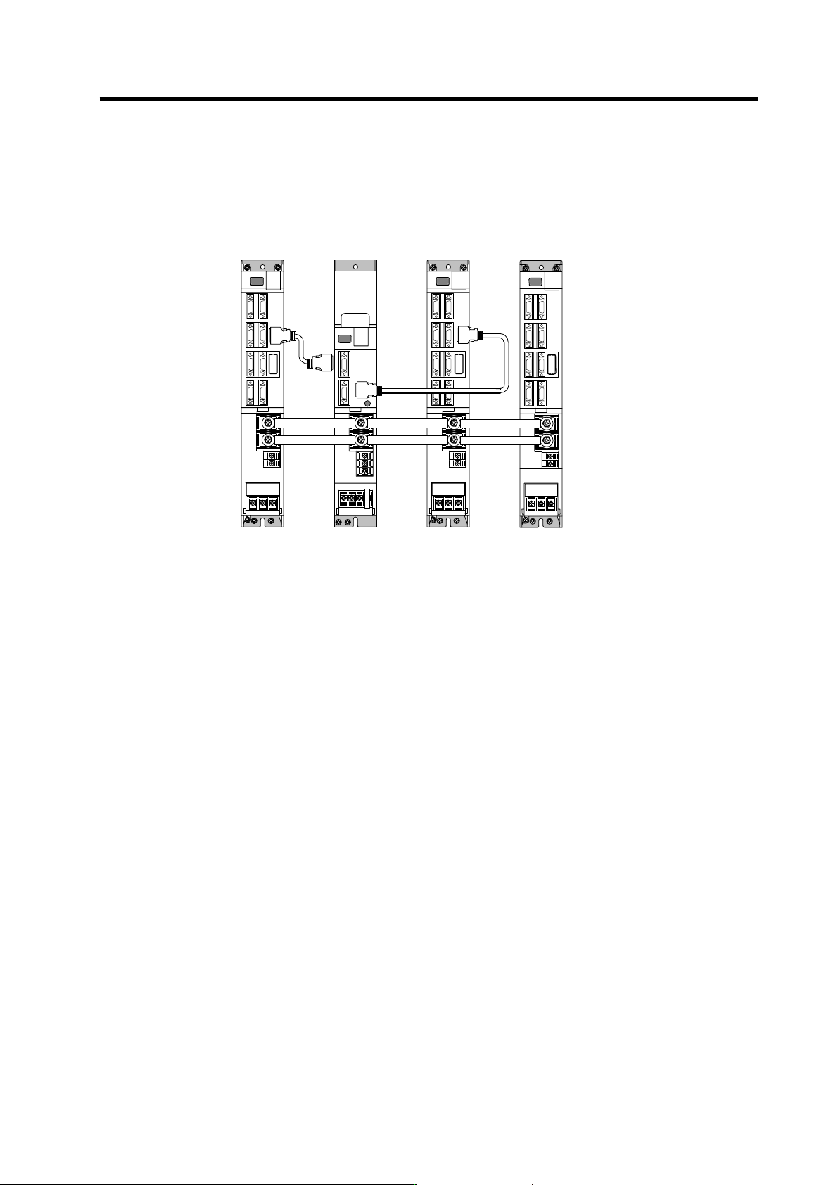
(3) When connecting two or more spindle drive units with one power supply unit
Connect units according to the following cautions.
MDS-C1-SPA
(
No.2
)
CN4
CN4
MDS-C1-SPA
(No.1)
MDS-C1-CV
CN9
CN4
MDS-C1-SPA
(
No.3
)
Connections when sharing one power supply
(Note 1) Connecting power supply unit and spindle drive unit.
Connect C1-CV CN4 and C1-SPA (No. 1) CN4 to C1-CV CN9 and C1-SPA (No.2) CN4. If
C1-SPA is connected with three or more axes, leave CN4 for C1-SPA (No. 3) and
following open.
Note that the C1-CV can be controlled (READY ON/OFF, alarm display, etc.) only by the
spindle drive unit connected to C1-CV CN4.
(Note 2) Make sure that the machine ready complete input turns ON and OFF simultaneously for all
the spindle drive units. Do not allow the signal to turn ON and OFF for only one spindle
drive unit.
(Note 3) When turning the machine ready complete input OFF during an emergency stop, always
have all the spindle drive units output the zero speed signal before turning the signal OFF.
(Note 4) If an alarm occurs in one of the spindle drive units, turn OFF the machine ready complete
input OFF for all the spindle drive units.
(Note 5) When connecting three or more spindle drive units, install the large-capacity spindle drive
units on both sides of the power supply unit.
2. Wiring and Connection
2 - 14
2-4 Motor and detector connection
2-4-1 Connection of the spindle motor
Refer to each motor specifications for details on the motor side connection destination, specifications
and outline, and for the spindle PLG detector specifications.
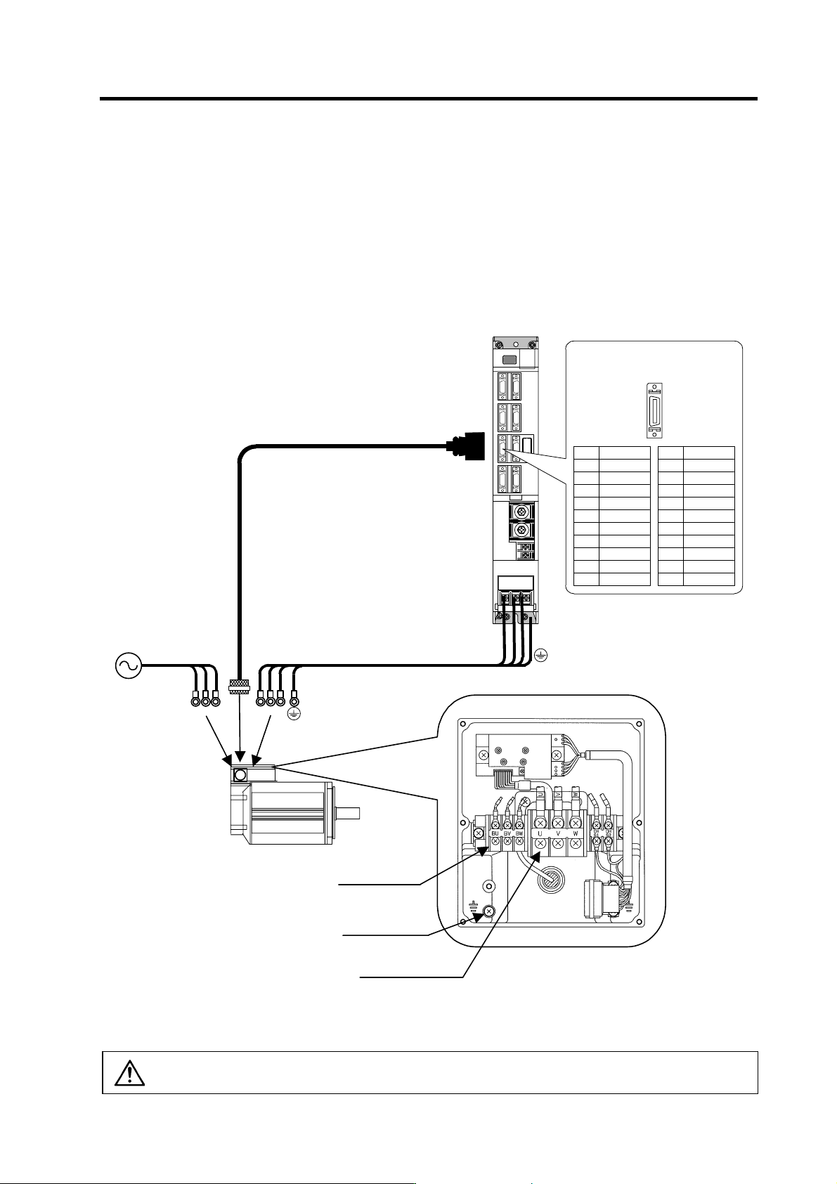
(1) Connecting the motor built-in PLG
U VW
Max. 30m
U V W
CN5
Spindle mot or
MDS-C1-SPA
Power c able
Option cable : CNP5
BU BW BV
C oolin g fan termin al
block (BU,BV,BW)
Gr ounding termin a l
Motor power terminal
block (U,V,W)
Example for 3-phase cooling fan
power s upp l y
(Note)
Either a single-phase or 3-phase power su pply is used for the cooling fan.
Refer to the Spin dle Motor Specifi cations for details.
Pin No.
Detector connector : CN5
No.1
No.10
No.11
No.20
Name
RG
N15(-15V)
RA
RB
Pin
11
12
13
14
15
16
17
18
19
20
Name
LG
MOH
P15(+15V)
PA
PB
PZ
Pin
1
2
3
4
5
6
7
8
9
10
CAUTION
The shield of spindle detector cable is not FG. Do not ground.
2. Wiring and Connection
2 - 15
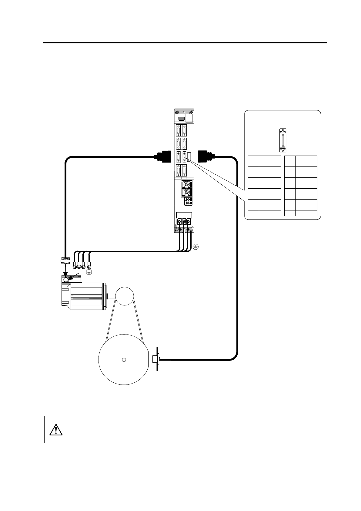
(2) Connecting the magnetic sensor
Refer to section (1) for connection with the spindle motor.
Name
P15(+15V)
MAG
LS
Pin
1
2
3
4
5
6
7
8
9
10
MDS-C1-SPA
Option cable : CNP6M
Option cable : CNP5
U VW
U V W
CN5
Spindle m otor
Magnetic sen s or
Power cable
Max. 30m
CN6
Spindle
Pin No.
Detector connector : CN6
No.1
No.10
No.11
No.20
Name
LG
MAGR
LSR
Pin
11
12
13
14
15
16
17
18
19
20
CAUTION
1. The shield of spindle detector cable is not FG. Do not ground.
2. The magnetic sensor orientation is not available with a machine having a
gear ratio between the motor and spindle exceeding 1:31.