MDS-C1-SPA Series INSTRUCTION MANUALib1500152(eng)a.pdf - 第22页
1. Installation 1 - 7 1-2-6 Heat radiation countermeasures In order to secure reliability and life, design the temperature in the panel so that the ambient temperature of each unit is 55°C or less. If heat accumulates at…
1. Installation
1 - 6
1-2-5 Heating value
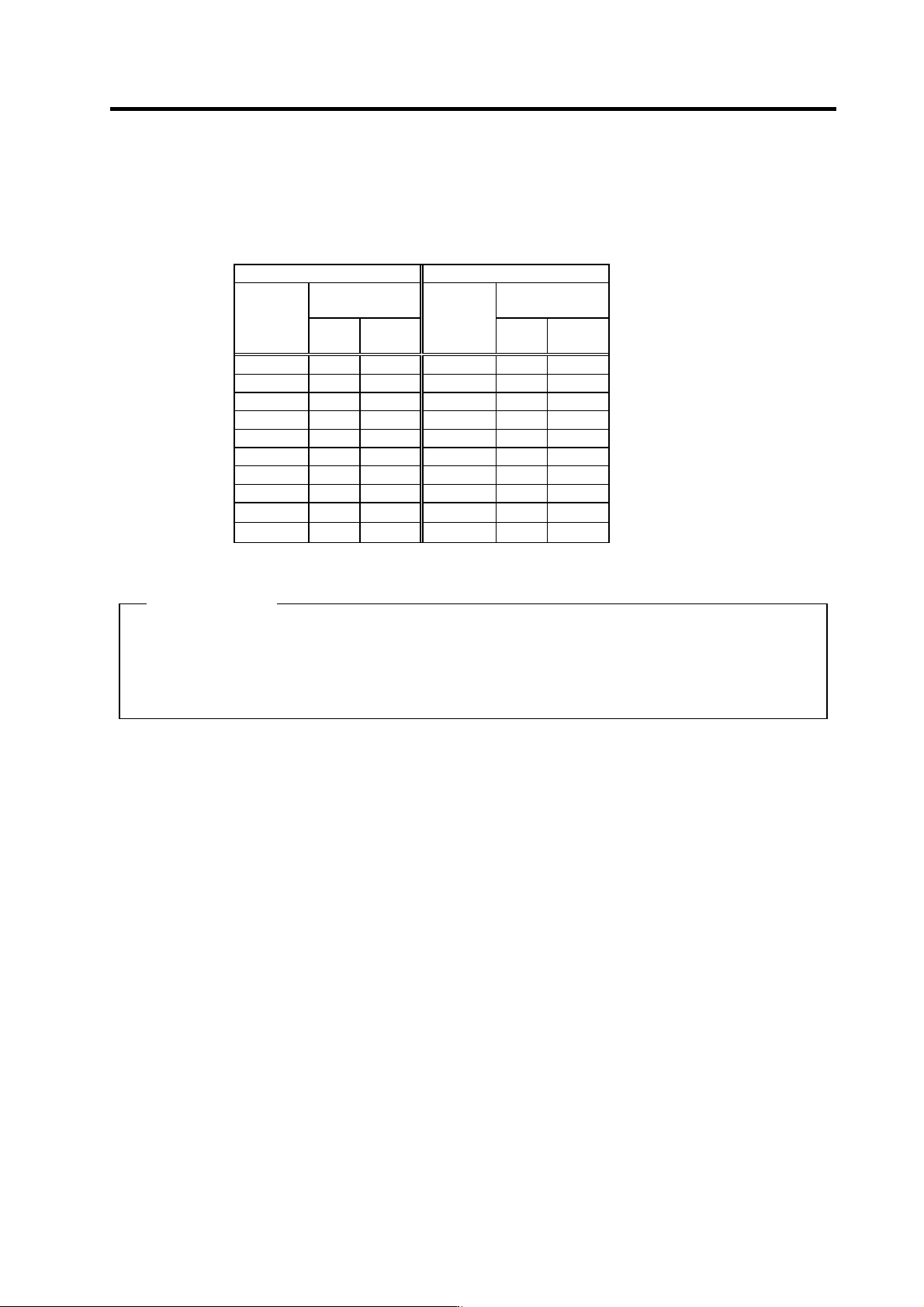
Each heating value is calculated with the following values.
The values for the spindle drive unit are for a continuous rated output. The value for the power supply
unit includes the AC reactor's heating value.
Servo drive unit Power supply unit
Heating amount
[W]
Heating amount
[W]
Type
MDS-C1-
Inside
panel
Outside
panel
Type
MDS-C1-
Inside
panel
Outside
panel
SPA- 55 31 76 CV- 37 21 34
SPA- 75 35 102 CV- 55 23 42
SPA-110 41 140 CV- 75 25 55
SPA-150 48 187 CV-110 26 99
SPA-185 62 280 CV-150 29 126
SPA-220 65 301 CV-185 33 162
SPA-260 80 403 CV-220 35 175
SPA-300 98 522 CV-260 40 220
CV-300 46 274
CV-370 54 346
(Example 1)
When using MDS-C1-CV-185, MDS-C1-SPA[]-185[]
Total heating value = (33+162) + (62+280)
= 537 [W]
Heating value in panel = (33) + (62)
= 95 [W]
1. Installation
1 - 7
1-2-6 Heat radiation countermeasures
In order to secure reliability and life, design the temperature in the panel so that the ambient
temperature of each unit is 55°C or less.
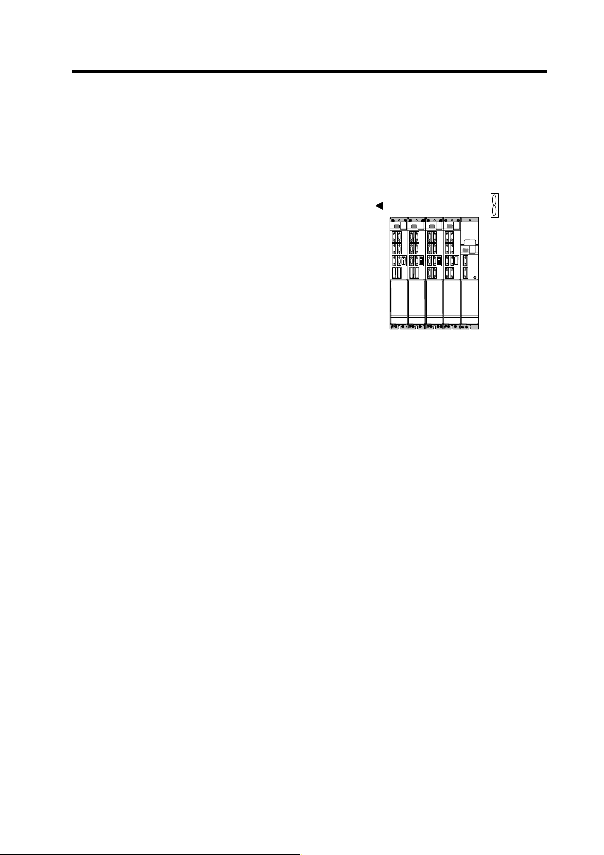
If heat accumulates at the top of the unit, etc., install a fan so that the temperature in the panel remains
constant.
(Note) Due to the structure, heat easily accumulates at the
top of the unit. Install a fan in the power distribution
panel to circulate the heat at the top of the unit.
Fan
(Ins ide panel)
Wind speed 2m/ s or more
1. Installation
1 - 8
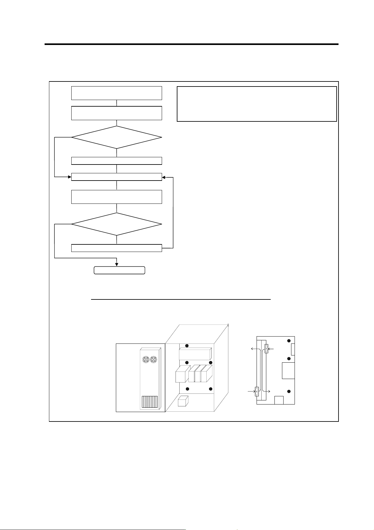
Please refer to following method for heat radiation countermeasures.
Heat
exchange
r
Unit
Flow of air
Flow of air
Relay, etc
Examples of mounting and temperature measurement positions (reference)
z
Measurement position (example)
Calculate total heat radiation of each
mounted unit (W)
Comparison of W and W1
W ≤ W1
Collection of internal temperature rise
distribution data
Mounting design
Improvements
Completion
Selection of heat exchanger
Evaluation
W>W1
∆T
≤10°C
∆T>10°C
Calculate cabinet’s cooling capacity
(W1)
<Hypothetical conditions>
(1) Average temperature in cabinet : T ≤ 55°C
(2) Cabinet peripheral temperature : Ta ≤ 0°C to 45°C
(3) Internal temperature rise value : ∆T =T–Ta
max= 10°C
<Supplement>
1) Refer to Specifications Manual, etc. for the heat
generated by each unit.
2) Enclosed cabinet (thin steel plate) cooling capacity
calculation equation
W1 = U × A × ∆T
U: 6W/m
2
×
°C (with internal agitating fan)
4W/m
2
× °C (without internal agitating fan)
A: Effective heat radiation area (m
2
)
(Heat dissipation area in panel)
Sections contacting other objects are excluded.
∆T: Internal temperature rise value (10°C)
3) Points of caution for heat radiation countermeasures
when designing mounting state
• Layout of convection in panel
• Collect hot air at suction port in heat exchanger
cabinet.
4) Understanding the temperature rise distribution in the
panel
∆T (average value) ≤ 10°C
∆T
max (maximum value) ≤ 15°C
R (inconsistency) = (∆T
max – ∆Tmin) ≤ 6°C
(Evaluate existence of heat spots)