MDS-C1-SPA Series INSTRUCTION MANUALib1500152(eng)a.pdf - 第23页
1. Installation 1 - 8 Please refer to following method for heat radiation countermeasures. Heat exchange r Unit Flow of air Flow of air Relay, etc Examples of mount ing and temperature measurement positions (reference) z…
1. Installation
1 - 7
1-2-6 Heat radiation countermeasures
In order to secure reliability and life, design the temperature in the panel so that the ambient
temperature of each unit is 55°C or less.
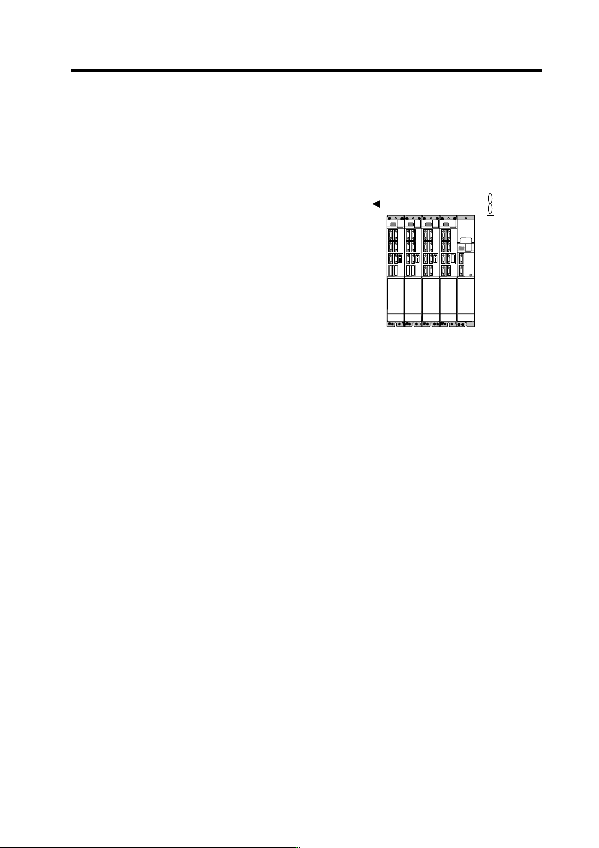
If heat accumulates at the top of the unit, etc., install a fan so that the temperature in the panel remains
constant.
(Note) Due to the structure, heat easily accumulates at the
top of the unit. Install a fan in the power distribution
panel to circulate the heat at the top of the unit.
Fan
(Ins ide panel)
Wind speed 2m/ s or more
1. Installation
1 - 8
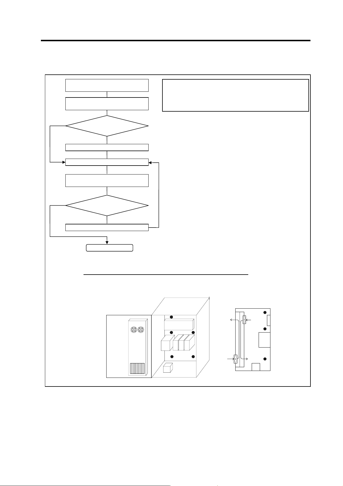
Please refer to following method for heat radiation countermeasures.
Heat
exchange
r
Unit
Flow of air
Flow of air
Relay, etc
Examples of mounting and temperature measurement positions (reference)
z
Measurement position (example)
Calculate total heat radiation of each
mounted unit (W)
Comparison of W and W1
W ≤ W1
Collection of internal temperature rise
distribution data
Mounting design
Improvements
Completion
Selection of heat exchanger
Evaluation
W>W1
∆T
≤10°C
∆T>10°C
Calculate cabinet’s cooling capacity
(W1)
<Hypothetical conditions>
(1) Average temperature in cabinet : T ≤ 55°C
(2) Cabinet peripheral temperature : Ta ≤ 0°C to 45°C
(3) Internal temperature rise value : ∆T =T–Ta
max= 10°C
<Supplement>
1) Refer to Specifications Manual, etc. for the heat
generated by each unit.
2) Enclosed cabinet (thin steel plate) cooling capacity
calculation equation
W1 = U × A × ∆T
U: 6W/m
2
×
°C (with internal agitating fan)
4W/m
2
× °C (without internal agitating fan)
A: Effective heat radiation area (m
2
)
(Heat dissipation area in panel)
Sections contacting other objects are excluded.
∆T: Internal temperature rise value (10°C)
3) Points of caution for heat radiation countermeasures
when designing mounting state
• Layout of convection in panel
• Collect hot air at suction port in heat exchanger
cabinet.
4) Understanding the temperature rise distribution in the
panel
∆T (average value) ≤ 10°C
∆T
max (maximum value) ≤ 15°C
R (inconsistency) = (∆T
max – ∆Tmin) ≤ 6°C
(Evaluate existence of heat spots)
1. Installation
1 - 9
1-3 Installing the spindle detector
1-3-1 Magnetic sensor
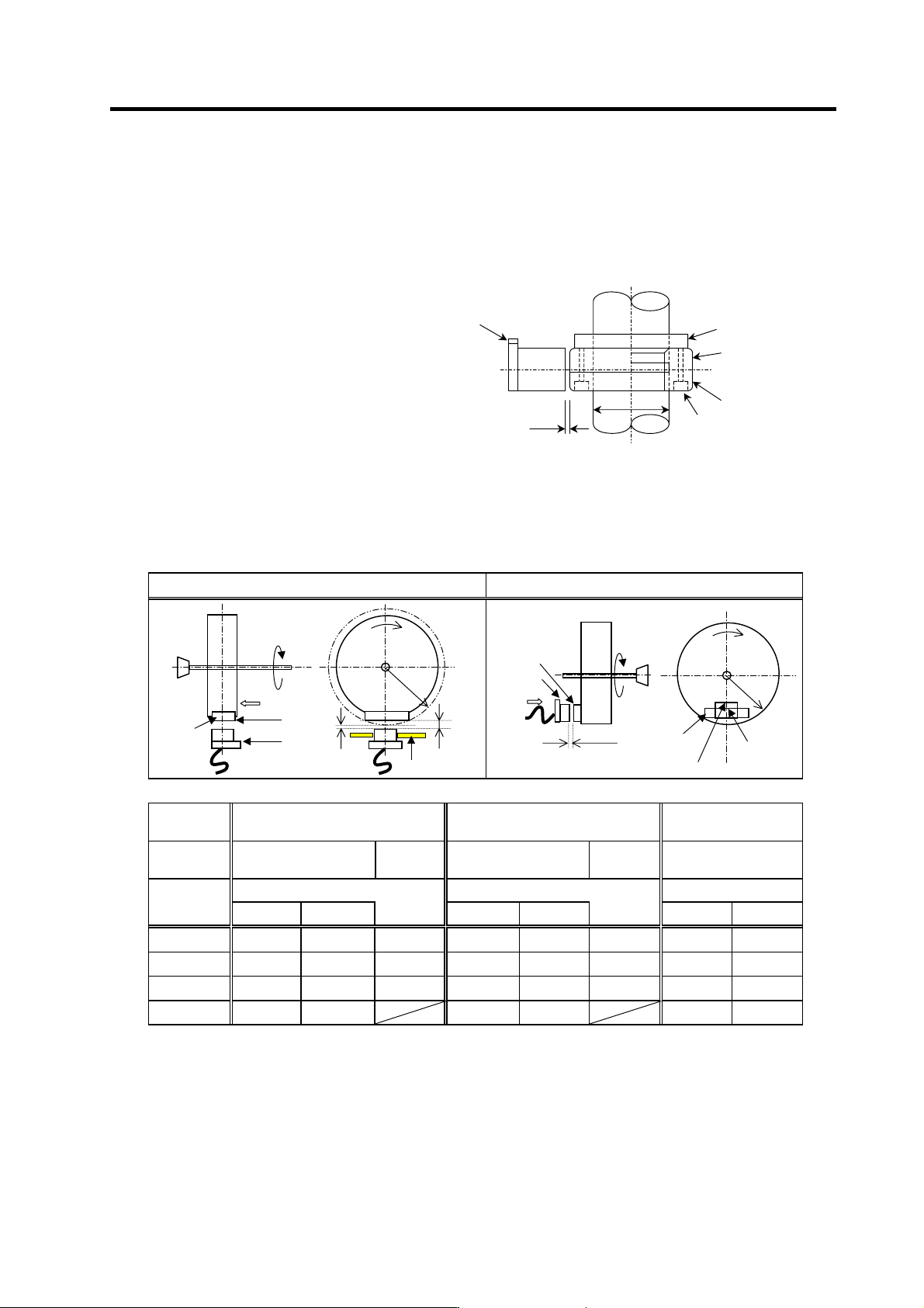
(1) Installing the magnetic sensor
• Tolerance to shaft dimension should
be "h6" on the part for installing a
magnet.
• 2-øG hole can be used for positioning
of spindle and magnet.
• Magnet shall be installed as shown to
the right.
• Misalignment between sensor head
and magnetic center line shall be
within ±2mm.
• There is an NS indication on the side of
the cover. Install so that the reference
notch on the sensor head comes to the
case side.
Gap
Reference notch
Reference drawing for magnet installat i on
G hole
h6
Spindle
Case
Cover
Spindle damping scre
w
(2) Gap between magnet and sensor
Circumference installation
Horizontal installation
Magnet
model
BKO-C1810H03 BKO-C1730H06 BKO-C1730H09
Installation
direction
Circumference
installation
Horizontal
installation
Circumference
installation
Horizontal
installation
Circumference
installation
Gap mm Gap mm Gap mm
R (Radius)
mm
Max. value Min. value Max. value Min. value Max. value Min. value
40 11.5±0.5 2.7±0.5 6.0±0.5 10.0±0.5 1.22±0.5 5.0±0.5 6.25±0.5 3.30±0.5
50 9.5±0.5 2.8±0.5 6.0±0.5 8.0±0.5 1.31±0.5 5.0±0.5 6.00±0.5 3.70±0.5
60 8.5±0.5 3.0±0.5 6.0±0.5 7.0±0.5 1.50±0.5 5.0±0.5 5.75±0.5 3.85±0.5
70 8.0±0.5 3.4±0.5 7.0±0.5 2.38±0.5 5.50±0.5 3.87±0.5
Reference
hole
Reference
notch
Magnet
Min. gap
Max. gap
Mounting plate
R
Direction of
rotation
NS
Spindle
Face A
Face A
Magnet
Gap
R
N
S
Spindle
Face B
Face B
Reference
hole
Reference
hole
Reference
notch
Direction of
rotation
Reference
notch