MDS-C1-SPA Series INSTRUCTION MANUALib1500152(eng)a.pdf - 第53页
2. Wiring and Connection 2 - 25 2-6-2 Output interface (1) External contact output circuit The drive unit fault output signal FA(CN 12-10) and FC(CN12-20) are the outputs. Use the contacts with the rating indicated below…
2. Wiring and Connection
2 - 24
(2) Encoder (1024p/rev) input interface
When connecting an encoder, +5V must be supplied from the drive unit side.
Power does not need to be supplied from the NC(PC) side.
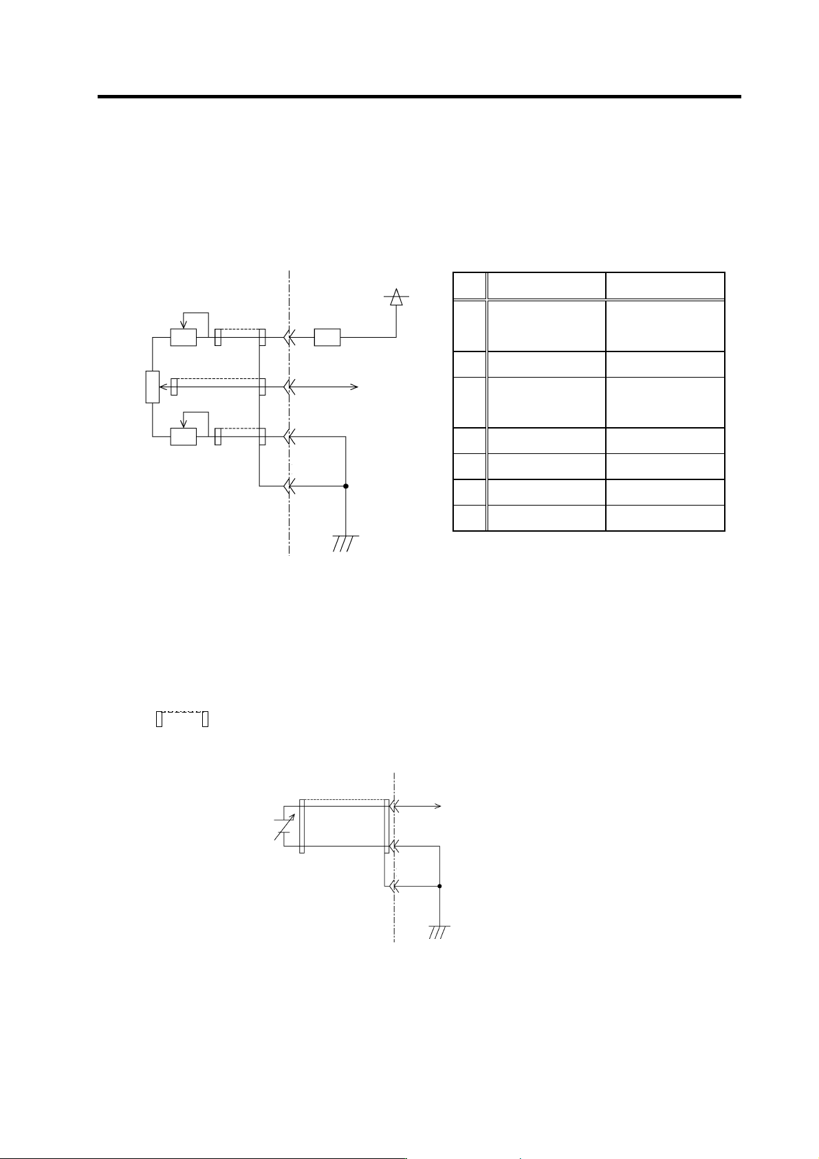
(3) Analog input interface
Analog speed
command input
Override input
VR1
Upper speed limit
setting
Not required
VR2 Analog speed setting Override s peed setting
VR3
Lower speed limit
setting
Not required
A RP (CN8A-6) OR3 (CN8A-16)
B SE1 (CN8A-7) OR2 (CN8A-17)
C SE2 (CN8A-8) OR1 (CN8A-18)
D SES (CN8A-5) ORS (CN8A-15)
Input impedance of input pin B (SE1, OR2):
Approx. 10K
Ω
NC(PC) side Drive unit side
1K
Ω
+15V
680
Ω
A
B
C
D
VR1
VR3
1K
Ω
VR2
2K
Ω
(Note 1) The figure above indicates the case of unipolar input. (Bipolar input cannot be created only with the power supply from the
drive unit side.)
(Note 2) +15V power supply is output from the input pin A (RP, OR3) via the resistance.
(Note 3) Input voltage tolerable value of the input pin B (SE1, OR2) is as follows.
SE1: ±12V
OR2: 0 to +12V
(Note 4) Make sure to use a shielded cable for the cable connecting to each input pin and provide with shield treatment.
(
represents for a shield.)
(Note 5) If there is a separate analog speed input command (or override input) power supply, connection will be as shown below.
NC(PC) side
Drive unit side
B
C
D
2. Wiring and Connection
2 - 25
2-6-2 Output interface
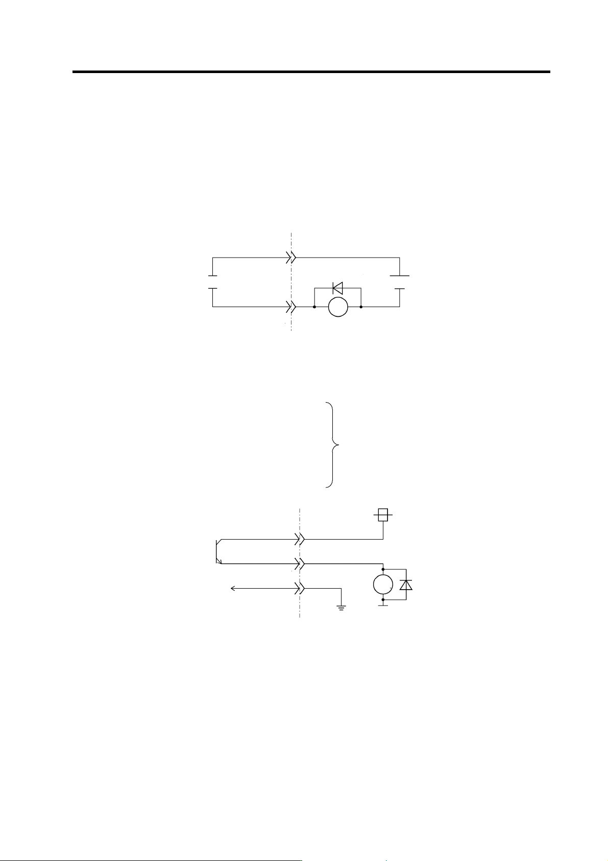
(1) External contact output circuit
The drive unit fault output signal FA(CN12-10) and FC(CN12-20) are the outputs.
Use the contacts with the rating indicated below.
24VDC 0.3A or less
Chattering 5ms or less
Compact relay is used. When connecting an inductive load such as relay, preferably use a DC
compact relay, and connect a flywheel diode in parallel with the coil as shown in the figure below.
NC(PC) side Drive unit side
FC(CN12-20)
FA(CN12-20)
Flywheel diode
24V
RA
(2) Open emitter output circuit
The followings are the open emitter outputs.
General-purpose output 1: OUT1 (CN11-7)
General-purpose output 2: OUT2 (CN11-17)
General-purpose output 3: OUT3 (CN11-8)
General-purpose output 4: OUT4 (CN11-18)
General-purpose output 5: OUT5 (CN11-9)
General-purpose output 6: OUT6 (CN11-10)
General-purpose output 7: OUT7 (CN11-20)
General-purpose output 8: OUT8 (CN9A-8)
Output transistor rating
M54630P TR array
Tolerable voltage 24VDC or less
Tolerable current 50mA or less
(per 1 output)
NC(PC) side Drive unit side
RG(CN10-10)
24V
RA
+24V(CN10-17)
OUT1 to 8
2. Wiring and Connection
2 - 26
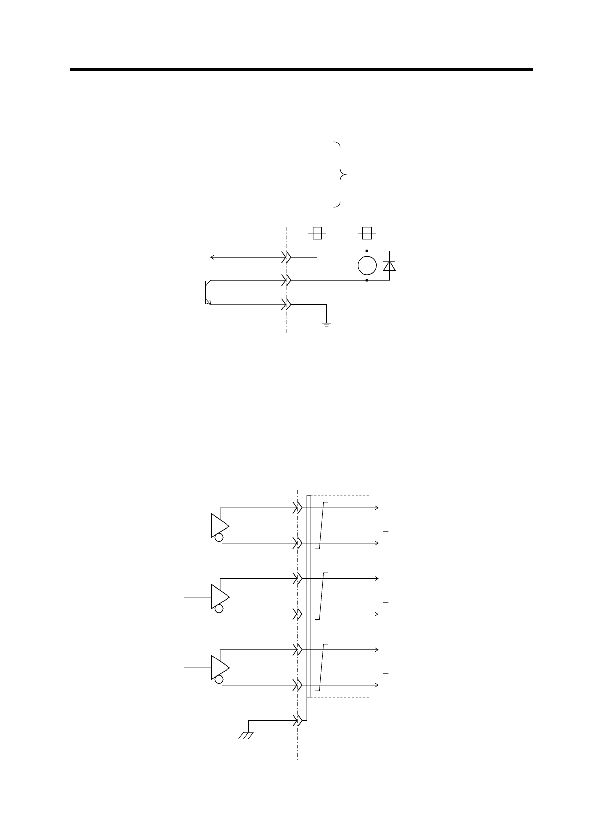
(3) Open collector output circuit
The followings are the open collector outputs.
General-purpose output 1C: OUT1C (CN12-7)
General-purpose output 2C: OUT2C (CN12-17)
General-purpose output 3C: OUT3C (CN12-8)
General-purpose output 4C: OUT4C (CN12-18)
General-purpose output 5C: OUT5C (CN12-9)
General-purpose output 6C: OUT6C (CN10-20)
Output transistor rating
M54633P TR array
Tolerable voltage 24VDC or less
Tolerable current 50mA or less
(per 1 output)
NC(PC) side Drive unit side
RG(CN10-10)
24V
RA
+24V(CN10-17)
OUT1C to 6C
24V
(Note 1) When using a DC relay externally, connect a flywheel diode in parallel with the coil.
(Note 2) 24V and RG are common for the open emitter and open collector output. Pay attention to the cable size. (24V and RG
consume 60mA only for the spindle drive unit internal circuit.)
(Note 3) When all 8 circuits are used for the open emitter output, the total current has to be no more than 350mA.
(Note 4) High-frequency noise due to chopper affect s this output signal and may cause the reception side of circuit for this signal to
malfunction. In such a case, use a shielded cable for the output signal connection cable, and connect one side of the
shielded cable to the spindle drive unit CN10-10 pin and the other one to the 24V power supply's ground.
(4) Pulse feedback output
Pulse feedback output is described as shown in the figure below.
(The output signal is equivalent of RS485.)
NC(PC) side Drive unit side
GND(CN8A-1)
SYZ*(CN8A-14)
SYZ(CN8A-4)
SYB*(CN8A-13)
SYB(CN8A-3)
SYA*(CN8A-12)
SYA(CN8A-2)
A
-phase
B-phase
Z-phase
A-phase
B-phase
Z-phase
(Note) Use an output IC equivalent of Motorola MC3487.