MDS-C1-SPA Series INSTRUCTION MANUALib1500152(eng)a.pdf - 第55页
2. Wiring and Connection 2 - 27 2-6-3 Spindle coil changeover There are spindle motors capable of coil changeover control, which enables favorable characteristics to be attained from low speeds to high s peeds by changin…
2. Wiring and Connection
2 - 26
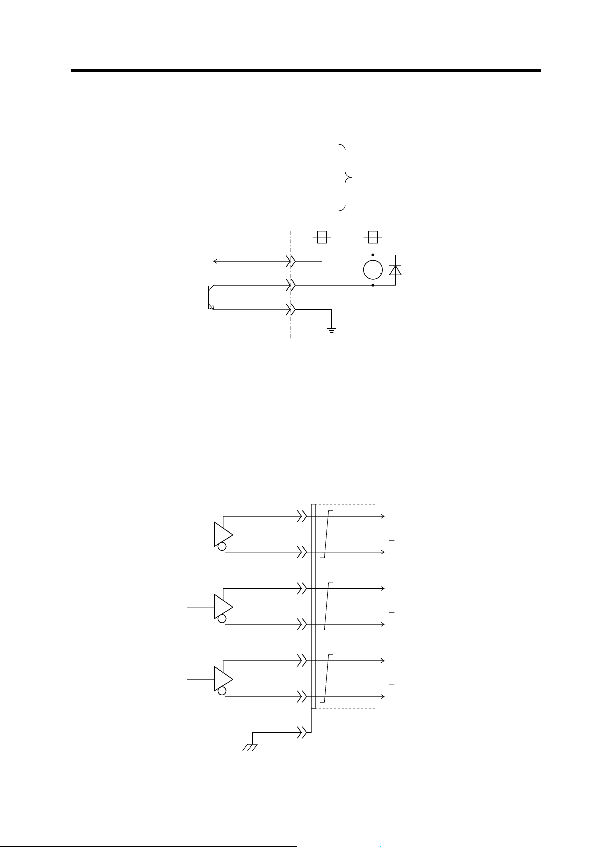
(3) Open collector output circuit
The followings are the open collector outputs.
General-purpose output 1C: OUT1C (CN12-7)
General-purpose output 2C: OUT2C (CN12-17)
General-purpose output 3C: OUT3C (CN12-8)
General-purpose output 4C: OUT4C (CN12-18)
General-purpose output 5C: OUT5C (CN12-9)
General-purpose output 6C: OUT6C (CN10-20)
Output transistor rating
M54633P TR array
Tolerable voltage 24VDC or less
Tolerable current 50mA or less
(per 1 output)
NC(PC) side Drive unit side
RG(CN10-10)
24V
RA
+24V(CN10-17)
OUT1C to 6C
24V
(Note 1) When using a DC relay externally, connect a flywheel diode in parallel with the coil.
(Note 2) 24V and RG are common for the open emitter and open collector output. Pay attention to the cable size. (24V and RG
consume 60mA only for the spindle drive unit internal circuit.)
(Note 3) When all 8 circuits are used for the open emitter output, the total current has to be no more than 350mA.
(Note 4) High-frequency noise due to chopper affect s this output signal and may cause the reception side of circuit for this signal to
malfunction. In such a case, use a shielded cable for the output signal connection cable, and connect one side of the
shielded cable to the spindle drive unit CN10-10 pin and the other one to the 24V power supply's ground.
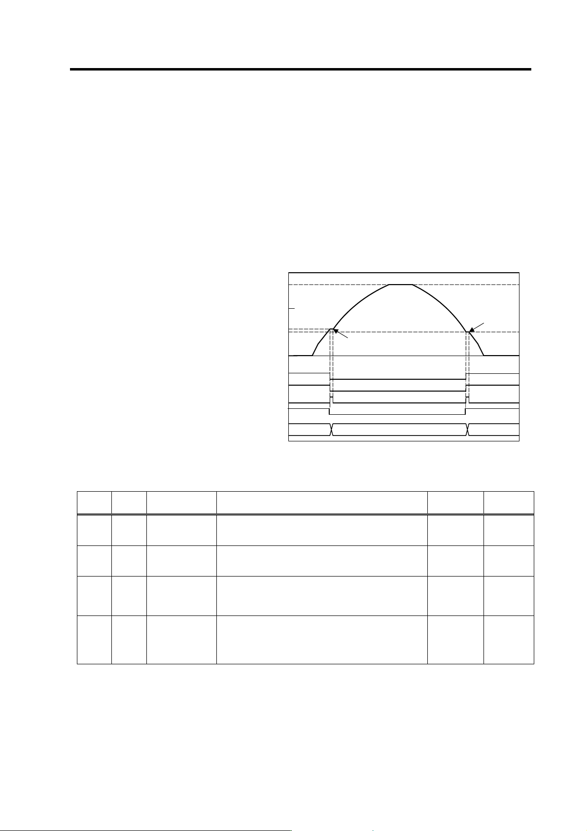
(4) Pulse feedback output
Pulse feedback output is described as shown in the figure below.
(The output signal is equivalent of RS485.)
NC(PC) side Drive unit side
GND(CN8A-1)
SYZ*(CN8A-14)
SYZ(CN8A-4)
SYB*(CN8A-13)
SYB(CN8A-3)
SYA*(CN8A-12)
SYA(CN8A-2)
A
-phase
B-phase
Z-phase
A-phase
B-phase
Z-phase
(Note) Use an output IC equivalent of Motorola MC3487.
2. Wiring and Connection
2 - 27
2-6-3 Spindle coil changeover
There are spindle motors capable of coil changeover control, which enables favorable characteristics to
be attained from low speeds to high speeds by changing two types of coils.
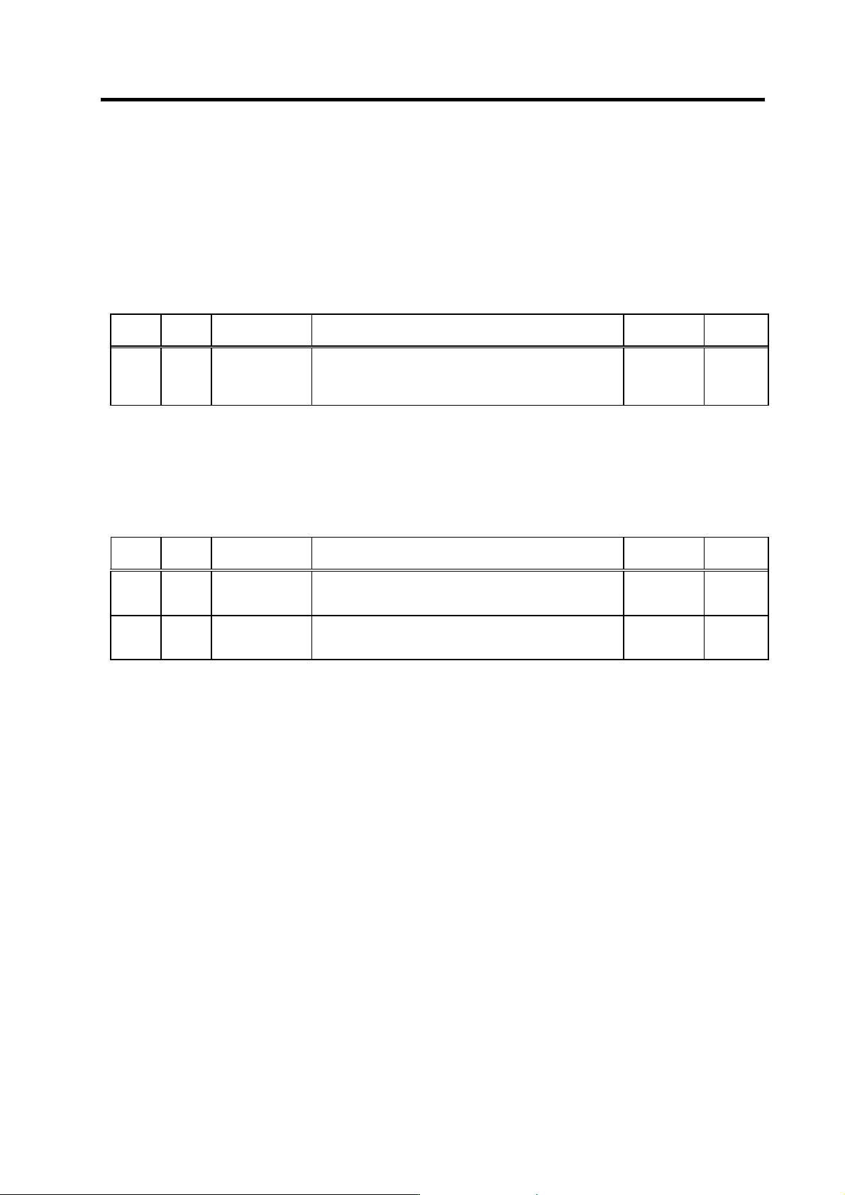
(1) Coil changeover control
The speed at which to change the coils is detected by the spindle drive according to the value set
with spindle parameter SP020. This is conveyed to the NC or PC with a speed detection (SD) signal.
The NC or PC judges the other conditions (coil fixed, etc.), and issue a coil changeover command
to the spindle drive with the L coil selection command (LCS).
To prevent the contactor from varying, the hysteresis set with SP047 is applied on the speed when
changing from the low-speed coil to the high-speed coil and the high-speed coil to the low-speed
coil.
Speed detection (SD1) [SPA→NC(PC)]
L coil selection command (LCS) [NC(PC)
→SPA]
Changing coil (MKC)
[SPA→NC(PC)]
In L coil selection signal (LCSA) [SPA
→NC(PC)]
Contactor changeover
0
2000
Time
6000
Spindle motor speed
(r/min)
4000
(SP020+SP047)
Low-speed coil High-speed coil Low-speed coil
SP020
Spindle motor coil changeover control
No. Abbrev. Parameter name Description Setting range
Standard
value
SP020 SDTS* Speed detection
set value
Set the motor speed of which speed detection 1 output is
performed. The setting value is determined by Mitsubishi
according to the specifications of coil changeover motor.
0 to 32767
(r/min)
Depends on
the motor to
be used.
SP047 SDTR* Speed detection
reset value
Set the reset hysteresis width for a speed detection set
value defined in SP020 (SDTS).
0 to 1000
(r/min)
Lath: 300
Machining:
100
SP129
to
SP140
HI01
to
HI12
General-purpose
input selection
Set the general-purpose input signals IN1 to IN12 as to
which function they should have. To have the coil
changeover function, set "18" (L coil selection command) in
one of those signals.
0 to 13
14 to 9
-
SP141
to
SP154
H01e
to
H01c
General-purpose
output selection
Set the general-purpose output signals OUT1 to OUT8
(open emitter) or OUT1C to OUT6C (open collector) as to
which function they should have. Set "18" (L coil selected
signal) in one of those signals. Also, set "16" (changing coil)
in another signal as required.
0 to 4
7 to 23
-
2. Wiring and Connection
2 - 28
(2) Protective functions
[1] Base shutoff after a winding changeover
When the L-coil selection command (LCS) is used to perform low-speed winding → high-speed
winding switching, or vice-versa, this base is shut off during contactor operation time in order to
protect the spindle drive unit's main circuit. This base shutoff time is determined by the "Winding
changeover base shutoff timer" (SP059) setting. The standard time setting should be used, as a
shorter time can cause contactor burn damage.
(Refer to 4-2-2 (4) "Spindle control output 4" Coil changing (bit 6) for details.)
No. Abbrev. Parameter name Description Setting range
Standard
value
SP059 MKT* Winding
changeover base
shut-off timer
Set the base shut-off time for contactor switching at coil
changeover.
Note that the contactor may be damaged with burning if the
value of this parameter is too small.
50 to 10000
(ms)
150
[2] Current limit after coil changeover
Following a coil changeover, the current is limited (SP061) for the period specified by the
current limit timer (SP060) in order to stabilize control. When the synchronous tap control is
executed immediately after the coil changeover, the output current is limited to the value set in
SP061, therefore apply the sequence to execute the position control after the current limit is
cancelled.
No. Abbrev. Parameter name Description Setting range
Standard
value
SP060 MKT2* Current limit timer
after coil
changeover
Set the current limit time to be taken after completion of
contactor switching at coil changeover.
0 to 10000
(ms)
500
SP061 MKIL* Current limit value
after coil
changeover
Set the current limit value during a period defined in SP060
(MKT2) after completion of contactor switching at coil
changeover.
0 to 120 (%) 75