MDS-C1-SPA Series INSTRUCTION MANUALib1500152(eng)a.pdf - 第160页
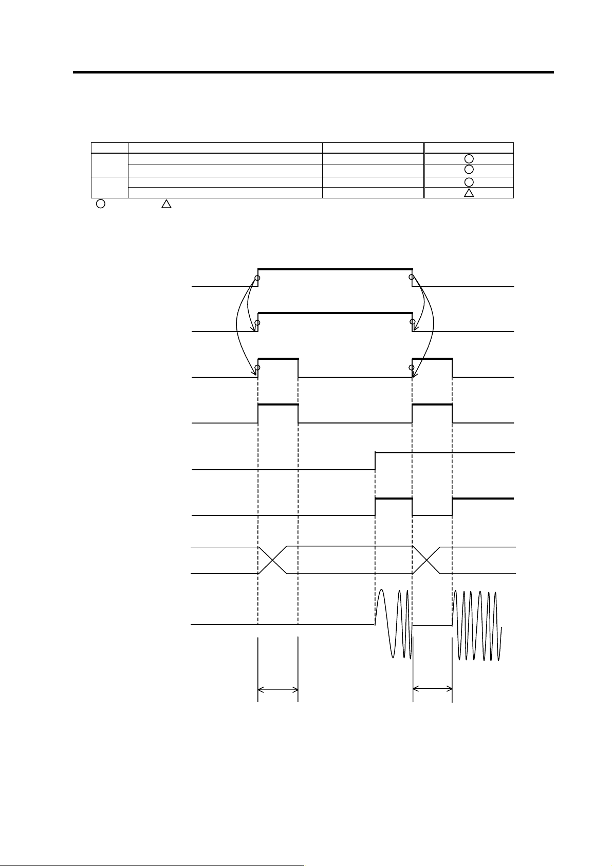
4. Spindle Adjustment 4 - 69 4-3-6 Adjusting coil changeover (1) Necessary input/output I/O Signal name I/O mode Mandatory/Opti onal L coil selection command signal (LCS) General-purpose input Input Forward run signal (S…
4. Spindle Adjustment
4 - 68
(9) Synchronous tapping operation
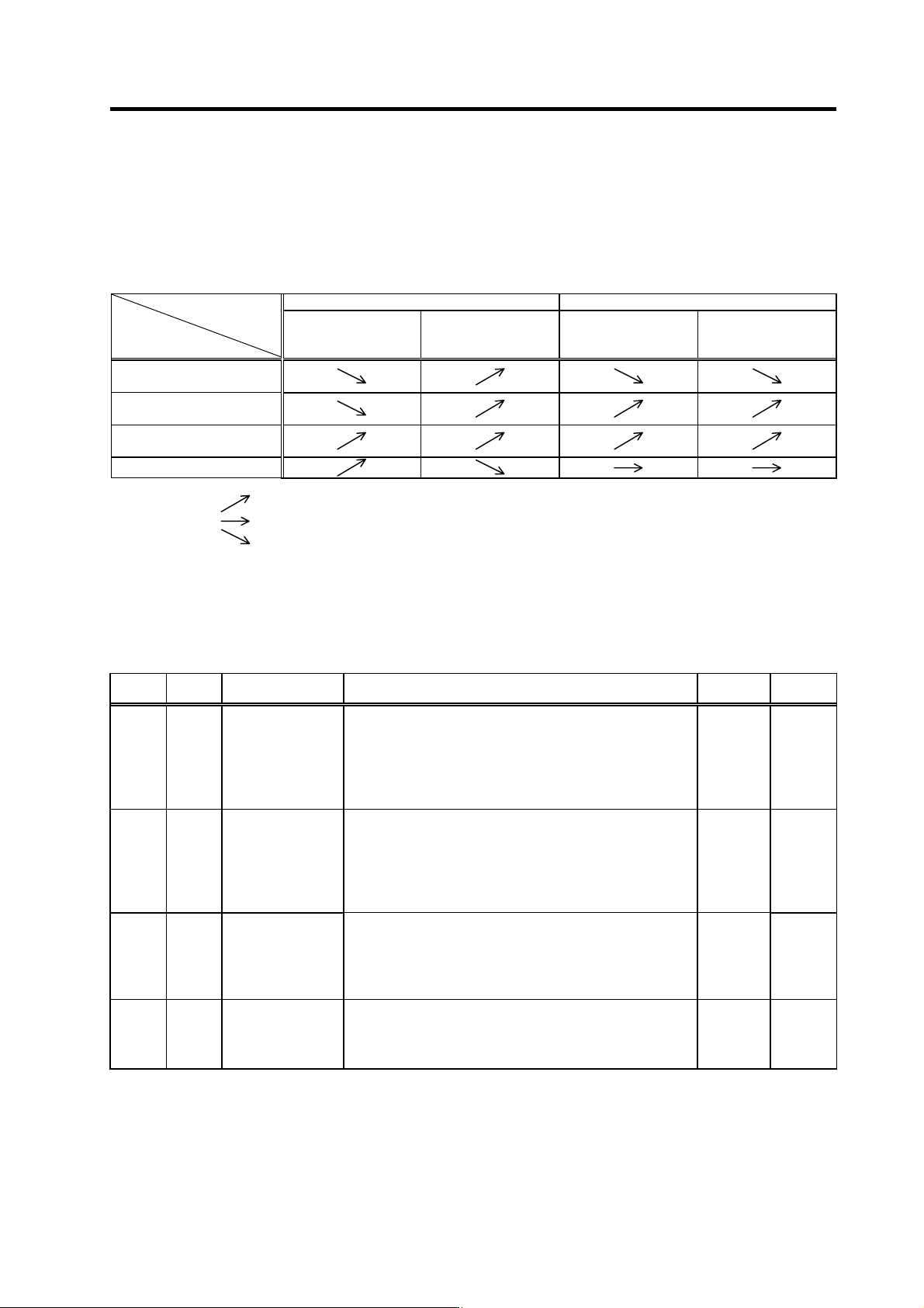
Carry out trial operation after setting the parameters. Carry out dry operation without tapping or a
workpiece, and confirm the amount that the spindle moves in respect to the servo axis. If there is
no problem, proceed with actual cutting operation. If there any problem occurs during dry run
operation or actual cutting operation, refer to the following table and change the settings
accordingly.
NC side setting Spindle drive unit side setting
Position loop gain
Acceleration/
deceleration time
constant
SP172(VGHP)
SP173(VGHI)
SP174(HPYV)
Gear noise is louder than
one in regular operation
The spindle undershoots
or overshoots
Machining accuracy is
poor
Machining time is long
(Note 1) The meaning of the arrows above is as described below.
: Increase the setting value
: Do not change the setting value
: Decrease the setting value
(Note 2) When the gear noise is large in standard setting, and the machining precision deteriorates as the speed loop gain is
decreased, if the motor maximum speed during S analog high-speed tapping is lower than the regular motor maximum
rotation speed, those conditions may be solved by setting a smaller value than SP017(TSP) in SP171(HSPT).
Note that, in this case, the spindle (or the motor) maximum speed during the NC side S analog high-speed tapping must be
changed. Thus, analog speed command offset and analog speed command gain must be adjusted again.
Related spindle parameters
No. Abbrev. Parameter name Description
Setting
range
Standard
value
SP171 HSPT
S-analog
high-speed tapping
motor maximum
speed
Sets the maximum motor speed during S-analog high-speed
tapping.
When "0" is set, the value will be the one set in SP017(TSP).
Sets the maximum motor tapping speed here when the gear
noise is louder than during the regular speed loop operation, or
when you wish to improve the tapping accuracy.
0 to 32767
(r/min)
0
SP172 VGHP
S-analog
high-speed tapping
speed loop
proportional gain
Sets the speed loop proportional gain during S-analog
high-speed tapping.
The larger the value, the higher the responsiveness, but the
bigger the vibration or noise becomes.
When "0" is set, the value will be the one set in
SP022(VGNP1).
0 to 1000 0
SP173 VGHI
S-analog
high-speed tapping
speed loop integral
gain
Set s the speed loop integral gain during S-analog high-speed
tapping
If the value of SP172(VGHP) is set, set the value so that the
setting value’s proportion between SP172 and SP173 is 1:1.
When "0" is set, the value will be the one set in SP023(VGNI1).
0 to 1000 0
SP174 HPYV
S-analog
high-speed tapping
variable excitation
rate (min value)
Sets the minimum value of the variable excitation rate during
S-analog high-speed tapping.
Smaller value is set to suppress the gear noise, etc., and larger
value is set to improve the tapping accuracy.
0 to 100
(%)
0
4. Spindle Adjustment
4 - 69
4-3-6 Adjusting coil changeover
(1) Necessary input/output
I/O Signal name I/O mode Mandatory/Optional
L coil selection command signal (LCS) General-purpose input
Input
Forward run signal (SRN), reverse run signal (SRI) Dedicated input
L coil selected signal (LCSA) General-purpose output
Output
Changing coil signal (MKC) General-purpose output
: Mandatory : Optional
(2) Operation sequence
L coil select ion c ommand
signal (LCS)
L coil select ed s i gnal (LCS A )
ON
ON
OFF
OFF OFF
OFF
ON
OFF
Base cutoff hold
Changing coil signal (MKC)
Forward run (SRN), reverse run (S RI ) s i gnal
Base ON
Motor const ant s changeover
(parameter)
Output current waveform (approx.)
ON
OFF
OFF
ON
OFF
ON
OFF
OFF
ON
OFF
OFF
ON
OFF
ON
High-speed coil
Low-speed coil High-speed coil
T1
T1
T1: Base cutoff hold time (SP059 Standard setting:150ms)
4. Spindle Adjustment
4 - 70
[Outline of operation]
A coil of the motor is changed when using a coil changeover motor. When changing the coil, change
the contactor connected outside by turning L coil selection signal ON/OFF during motor operation or
motor stop.
CAUTION
1. The motor will be in an uncontrolled state after the L-coil selection signal
has turned ON/OFF until the coil is fully changed over. Thus, when
changing coils during heavily cutting operations, the motor speed may be
dropped significantly, or the motor may be stopped. When cutting surface
precision is required, do not perform coil changeove r or avoid cutting du ring
rotation in this period.
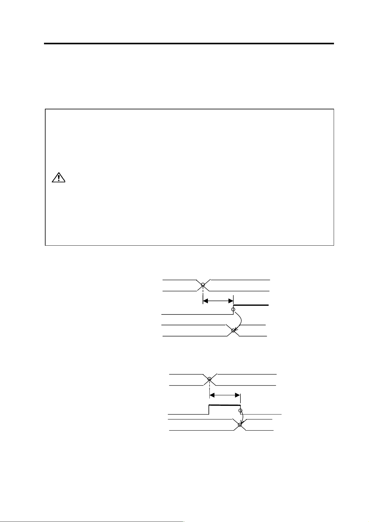
2. In T
1
(During base shut-off time) in the figure of the previous page, the
spindle drive unit does not accept any input signal (forward run start
command, reverse run start command, orientation start command). Thus,
input those signals to the spindle drive unit, having TM(=T
1
+50ms) or more
timer secured after the L coil sele ction command signal (LCS) has been
changed as shown in the drawing below.
Instead of using a timer, those signals can be input after the "cha nging coil"
signal (MKC) is turned ON from OFF.
3. Base shut-off time T
1
is determined with the parameter SP059 (MKT)
setting value. In connection with the contacto r operation, the st andard value
will be 150ms. Thus, TM usually has to be set to 200ms or more.
[1] Using a timer
L coil selection command
signal (LCS)
T
M
Coil changeover timer
Each input signal
T
M
≧200ms
[2] Using the "changing coil" signal (valid only when MDS-B-SPA is used)
L coil selection command
signal (LCS)
T
1
Changing coil signal
(MKC)
Each input signal